Knowledge Ark build sheet · Knowledge Ark · Culture Ark · An Artificial Mind Hive project by Austin Little
A hydraulic ram pump lifts water uphill using nothing but the energy of water flowing downhill. It has no motor, burns no fuel and uses no electricity. It has only two moving parts, both valves, and it can run day and night for years with a steady "clack, clack" as long as water keeps flowing into it. A stream with a small fall of one or two metres can drive a ram to push part of its water ten, twenty or more metres up a hill to a house, a garden or a tank. This sheet explains where the ram came from, how it uses the sudden pressure of water hammer, what each part does, how to work out how much water it will deliver, and how to build one from ordinary galvanised or PVC pipe fittings with a swing check valve and a spring or weighted waste valve.
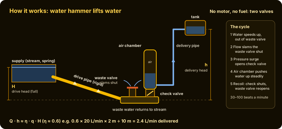
The working cycle. Water speeds up down the drive pipe and escapes through the waste valve until the flow slams it shut. The moving column of water stops suddenly, the pressure jumps, and a little water is forced through the check valve into the air chamber, which pushes it steadily up the delivery pipe. Then the waste valve drops open and the cycle repeats, usually 30 to 100 times a minute.
Why keep this in the Knowledge Ark
Lifting water is one of the hardest daily jobs in a world without power. Carrying it by hand is slow and exhausting, and pumps need fuel, electricity, wind or animals. A ram pump needs only a source of flowing water with some fall, such as a stream, spring or ditch, and the water to be lifted must be higher than the pump. Where that situation exists, a ram is one of the cheapest and most reliable ways known to move water uphill, and once it is running it costs almost nothing.
It is also a beautiful example of physics put to work. A ram shows that moving water carries momentum, that stopping it suddenly creates very high pressure, and that a small amount of water can be lifted a long way by trading away a larger amount of water falling a short way. The formula that describes it is a simple statement of conservation of energy. Understanding it helps with any piping system, because the same water hammer that drives a ram can burst pipes when it happens by accident.
History: how it came about
Water hammer, the accident behind the invention
Anyone who has shut a tap quickly in an old house has heard water hammer: a bang in the pipes as the moving water is stopped all at once. Water is heavy and almost incompressible, so when a moving column of it is brought to a halt, its momentum turns into a pressure surge that runs back along the pipe. Plumbers and engineers usually try to prevent this. The ram pump is the idea of using it on purpose.
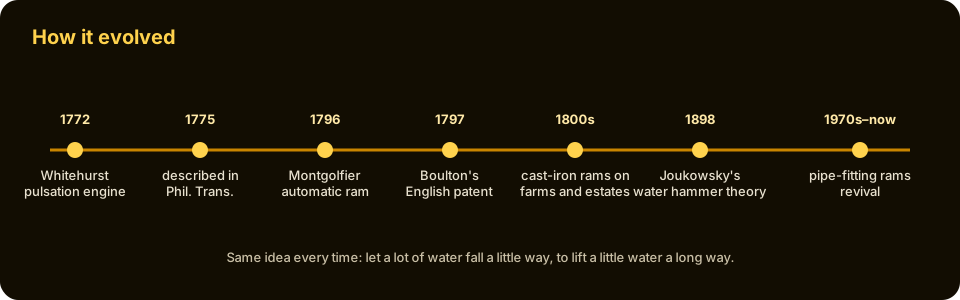
1772: John Whitehurst's pulsation engine
The first recorded machine to use water hammer to raise water was built in 1772 by John Whitehurst, a clockmaker and scientist from Derby, England, and a member of the Lunar Society, the circle of inventors and thinkers around Birmingham. He built it at Oulton in Cheshire to raise water from a spring to a brewhouse and other rooms higher up. He described it in the Philosophical Transactions of the Royal Society in 1775.
Whitehurst's machine was not automatic. Water ran down a long pipe from a supply to a tap in the kitchen below. Each time the tap was opened and shut, the sudden stop of the flowing water drove a little water through a valve into an air vessel and up a pipe to a cistern above. Because the kitchen tap was used many times a day, the cistern filled as a side effect of ordinary housework. The idea worked, but it depended on someone opening and closing the tap.
1796: Montgolfier's automatic hydraulic ram
The step that made the ram a true pump came in France. Joseph Michel Montgolfier, the papermaker who with his brother Jacques-Étienne had launched the first hot-air balloons in 1783, devised in 1796 a self-acting version that he called the bélier hydraulique, the hydraulic ram, because its repeated blows reminded him of a battering ram. His key addition was a valve that closed and reopened by itself, driven only by the flow of water and its own weight. With that, the ram could run continuously without anyone touching it.
Montgolfier used rams at his family's paper mill, and the invention spread. In England, the industrialist Matthew Boulton took out a patent on the ram in 1797. Montgolfier's son, Pierre François Montgolfier, later improved the design, including a small "snifter" valve that let a little air into the pump with each beat so that the air chamber did not slowly fill with water and stop working.
The nineteenth century: rams on farms and estates
Through the nineteenth and early twentieth centuries, cast-iron rams were made by manufacturers in Britain, France, the United States and elsewhere, and installed by the thousand. They supplied country houses, farms, villages, railway water tanks and gardens with running water from nearby streams. Many ran for decades, and some installed more than a century ago still work. They were valued because they needed no fuel and very little attention: a ram might be checked once a week to clear leaves from the intake.
Understanding water hammer
The theory caught up with the practice later. In 1898 the Russian scientist Nikolai Joukowsky published a study of water hammer, based on experiments with the water mains of Moscow, that explained how fast pressure waves travel in pipes and how large the pressure surge is when flow is stopped. His result, now called the Joukowsky equation, is still used to design pipelines and to understand rams.
Decline and revival
With the spread of rural electricity and cheap engine-driven pumps in the twentieth century, rams fell out of use in rich countries. They have had a revival since the 1970s and 1980s, especially in development work in hilly regions of Asia, Africa and Latin America, where engineers and charities have promoted locally built rams made from standard pipe fittings, and among homesteaders and farmers who want water without power bills. The basic design has hardly changed since Montgolfier.
How it works
The cycle, step by step
- Acceleration. The waste valve is open. Water runs down the drive pipe from the supply and out through the waste valve, getting faster and faster.
- Closure. When the water is moving fast enough, the drag of the flow pushes the waste valve shut. It slams closed in a fraction of a second.
- Water hammer. The whole column of water in the drive pipe is still moving, but it suddenly has nowhere to go. Its momentum produces a sharp rise in pressure inside the pump body, much higher than the pressure from the supply height alone.
- Delivery. The high pressure forces open the delivery check valve, and a little water passes into the air chamber, squeezing the air inside. The compressed air then pushes water steadily up the delivery pipe, even between beats.
- Recoil. When the column of water in the drive pipe has stopped and given up its energy, the pressure falls. The delivery check valve shuts to stop water from coming back out of the air chamber. A brief pressure wave rebounds up the drive pipe, the pressure in the body drops below normal for a moment, and the waste valve falls or is pushed open by its weight or spring.
- Repeat. Water starts flowing out of the waste valve again, and the cycle starts over, typically 30 to 100 times per minute.
Why the pressure is so high
When the flow is stopped suddenly, the pressure rise is described by the Joukowsky equation:
Pressure rise = density of water × speed of the pressure wave × change in flow speed
The pressure wave in water inside a steel pipe travels at roughly 1,200 to 1,400 metres per second; in a more flexible PVC pipe it is slower, often about 300 to 500 metres per second. So stopping water moving at 1 metre per second in a steel pipe can create a pressure surge of about 1,000 × 1,200 × 1 = 1.2 million pascals, or about 12 bar, in a fraction of a second. That is the equivalent of more than 100 metres of water height. This is why a ram can lift water far higher than the height of the fall that drives it, and also why the fittings must be strong.
The rule that governs every ram
A ram cannot create energy. Each second, the energy it receives is the energy of water falling the drive height, and the energy it gives out is the energy of a smaller amount of water lifted the delivery height. Using:
- q = drive flow, the water entering the pump through the drive pipe (litres per minute)
- H = drive head, the vertical fall from the supply water surface to the pump (metres)
- Q = delivered flow, the water pushed up the delivery pipe (litres per minute)
- h = delivery head, the vertical height from the pump to the outlet at the top (metres)
- η = efficiency, the fraction of energy that is usefully transferred (between 0 and 1)
the relationship is:
Q · h ≈ η · q · H, so Q ≈ η · q · H ÷ h
The water that is not delivered, q minus Q, flows out of the waste valve and can return to the stream.
The efficiency of a well-built ram is commonly between about 0.5 and 0.8 when the delivery head is only a few times the drive head, and lower, perhaps 0.2 to 0.4, when it is twenty or more times higher. For rough planning, many guides use 0.6. Engineers sometimes define efficiency in slightly different ways, measuring heads from the pump (the D'Aubuisson efficiency used above) or from the supply level (the Rankine efficiency), so numbers from different sources are not always directly comparable.
A worked example
A stream gives a fall of H = 2 metres to the pump site. The drive pipe can supply q = 20 litres per minute. The tank on the hill is h = 10 metres above the pump. With an efficiency of 0.6:
Q ≈ 0.6 × 20 × 2 ÷ 10 = 2.4 litres per minute
That is about 144 litres an hour, or about 3,450 litres a day, because a ram runs all day and night. Of the 20 litres per minute that enter, 17.6 flow back to the stream from the waste valve. The ram gives up a lot of water in exchange for height, but over 24 hours the small, steady trickle adds up.
What limits a ram
- Fall. A ram needs some drive head; many designs work with as little as about 1 metre, and more fall gives more power.
- Flow. The supply must give at least the drive flow without running dry, or the ram stops.
- Height ratio. Delivery head is often between 2 and 20 times the drive head. Higher ratios are possible but give very little water.
- Drive pipe. It must be rigid, straight and steadily sloping, so it carries the water hammer efficiently. Guides suggest a length of very roughly 6 to 12 times the drive head, or a length between about 150 and 1,000 times the pipe's internal diameter; too short and the water does not build enough momentum, too long and the cycle becomes slow and sluggish.
Parts and what each one does
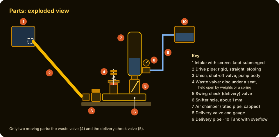
- Supply and intake. A pool, spring box, barrel or small dam on the stream, deep enough to keep the drive pipe's entrance under water, with a screen or strainer to keep out leaves, stones, fish and air. Air sucked into the drive pipe kills the water hammer.
- Drive pipe. A rigid pipe, preferably galvanised steel, running straight and steadily downhill from the intake to the pump. It carries the column of water whose momentum powers the ram. It is the most important part to get right.
- Pump body. A tee or set of fittings where the drive pipe ends and the two valves join it. A union or gate valve at the inlet lets you shut off the flow and take the pump apart.
- Waste valve (impulse valve). The valve that lets water escape and then slams shut when the flow is fast enough. It must reopen by itself, using a weight or a light spring. Its stroke (how far it opens) and its weight or spring tension are adjusted to tune the pump.
- Delivery check valve. A one-way valve, here a swing check valve, that lets water pass from the pump body into the air chamber on each pressure surge and stops it flowing back.
- Snifter (air valve). A very small hole or tiny valve just below the delivery valve that admits a little air on each recoil, replacing air that dissolves into the water in the air chamber.
- Air chamber. A capped, closed vessel, usually wider than the pipe, above the delivery check valve. The trapped air acts as a cushion: it absorbs each surge and pushes water up the delivery pipe smoothly. Without it the delivery would be violent and the pump would soon damage itself.
- Delivery valve and outlet. A gate or ball valve and fitting at the base of the air chamber where the delivery pipe connects, so the delivery can be shut off for maintenance, and ideally a pressure gauge.
- Delivery pipe. A smaller pipe, often flexible polyethylene, that carries the delivered water uphill to a tank. It can be long and follow the ground.
- Storage tank. A tank at the top that collects the delivered water, with an overflow so that the ram can keep running when the tank is full.
Build it: a 32 mm (1¼ inch) pipe-fitting ram
This build makes a small ram from standard threaded galvanised fittings, with PVC used for the air chamber. With a fall of 1.5 to 3 metres and a drive flow of roughly 20 to 40 litres per minute, it can typically deliver a few litres per minute to a height several times the fall. Size the parts to your site using the formula above.
Materials
- Drive pipe: 32 mm (1¼ inch) galvanised steel pipe long enough to reach from intake to pump in a straight line, typically 10 to 20 metres for a 1.5 to 3 metre fall. Heavy-walled PVC pressure pipe can be used but gives a softer water hammer and lower efficiency.
- Intake: a screen or strainer for the pipe entrance, and a barrel or small pool to keep it submerged.
- Inlet fittings: a 32 mm union and a 32 mm full-bore gate or ball valve.
- Pump body: two 32 mm tees, short 32 mm nipples, and reducers as needed.
- Waste valve: either a home-made poppet valve (described below) or a commercial or modified valve. The poppet uses a 32 mm tee or cap drilled for a seat, a bolt with a stiff rubber washer as the valve disc, nuts and washers as weights, or a light compression spring with an adjustable nut.
- Delivery check valve: one 32 mm brass swing check valve.
- Air chamber: a length of 75–100 mm (3–4 inch) pressure-rated PVC pipe about 60–90 cm long, with a glued end cap and a threaded adapter to the 32 mm fittings. Check that its pressure rating is well above your expected working pressure.
- Delivery outlet: a reducing tee, a 20 or 25 mm (¾ or 1 inch) ball valve, an optional pressure gauge, and a hose adapter.
- Delivery pipe: 20–25 mm polyethylene pipe long enough to reach the tank.
- Thread sealant tape or paste, PVC primer and cement, pipe wrenches, a drill with small bits, and a sturdy base such as a concrete pad or heavy timber with pipe clamps.
Step 1: survey the site
Measure the fall from the supply's water surface to the pump site with a level and measuring staff, a water-filled clear hose used as a level, or a surveyor's level. Measure the height from the pump site to where the tank will stand. Measure the stream flow in a dry season by timing how long it takes to fill a bucket. Use the formula to check that the delivered flow will be worth having. The ram must be placed below the supply, and its waste water must be able to drain away freely; it cannot work if it is flooded.
Step 2: build the intake and drive pipe
Make a small pool or set a barrel in the stream so the drive pipe entrance is at least 30 cm under water and screened. Lay the drive pipe in a straight line, sloping steadily downhill, with no high points where air could gather and no bends if at all possible. Anchor it firmly along its length, because it jumps with every beat if it is loose. Fit the union and the shut-off valve at its lower end.
Step 3: make the waste valve
The waste valve must be held open by gravity or a spring and pushed shut by the flow. A simple poppet design:
- Fit a tee onto the pump body with one branch pointing straight up. Cap the top of that branch with a fitting drilled with a clean round hole about 20–25 mm across: this hole is the valve seat, and water escapes up through it.
- Put a bolt through the centre of a stiff rubber disc slightly larger than the hole, sandwiched between metal washers, so the disc sits below the seat inside the fitting, with the bolt's shank passing up through the hole.
- On the part of the bolt above the seat, add nuts and washers as weights, or a light spring pressing down from a small bridge bracket. These hold the disc down, away from the seat, so the valve is open at rest.
- Add a lock-nut on the bolt that limits how far the disc can drop. That sets the stroke.
When water rushes up past the disc, its drag lifts the disc against the seat and the valve slams shut. When the pressure falls after each beat, the weight or spring pulls it open again. Some builders instead adapt a brass spring check valve or a swing check valve so that it hangs open by its own weight and is closed by the flow; the principle is the same.
Step 4: fit the delivery check valve and snifter
On the other branch of the pump body, fit the swing check valve so that it opens upward, letting water pass from the pump body into the air chamber but not back. Make sure the arrow on the valve points away from the pump body. Just below the check valve, in the pump body, drill a very small hole, about 1 millimetre across, as a snifter. On each recoil it draws in a tiny amount of air, which rises into the air chamber. If it spits a lot of water, it is too big; it should give only a small hiss and drip.
Step 5: fit the air chamber and delivery outlet
Above the check valve, fit the reducing tee. Screw the threaded adapter of the PVC air chamber into the top and glue its cap firmly; let the cement cure fully. Fit the delivery ball valve, gauge and hose adapter on the side branch, and connect the delivery pipe. Run the delivery pipe uphill to the tank, with an overflow at the tank leading back to a watercourse.
Step 6: mount it solidly
Bolt or clamp the pump to a concrete pad or heavy timber base. Every beat is a sharp blow, and a loose pump wastes energy and shakes fittings apart. Make sure the waste valve's outflow can drain away without flooding the pump.
First water: test and adjust
- Prime it. Close the delivery valve. Open the drive pipe valve and let water flow out through the waste valve.
- Start it. Push the waste valve shut by hand, let it go, and repeat a few times. It should start beating by itself with a regular clack. If it stops, check for air in the drive pipe or a valve that is too heavy or too light.
- Open the delivery. Slowly open the delivery valve. Water should begin to climb the delivery pipe; the gauge will show the pressure rising to match the height of the outlet.
- Tune the waste valve. A longer stroke or heavier weight gives slower, harder beats with more drive flow and usually more delivery; a shorter stroke or lighter weight gives faster, lighter beats using less water. Adjust in small steps and measure delivered flow with a bucket and a watch at the tank.
- Measure efficiency. Time how long the waste valve takes to fill a bucket and how long the delivery takes. Add them for drive flow, then use η = (Q × h) ÷ (q × H). Most well-tuned rams fall somewhere between 0.4 and 0.8.
- Troubleshooting. A ram that slows and stops after hours or days often has a waterlogged air chamber: check the snifter, or drain the air chamber and restart. A weak, irregular beat points to air in the drive pipe, a flexible or leaky drive pipe, or a blocked intake. Leaves and grit stuck in either valve stop it at once; clean the intake screen regularly.
Safety
- Water hammer is powerful. Pressure surges can be many times the static pressure. Use pipes, fittings and air chambers rated well above the working pressure, never use thin-walled or damaged pipe, and never use a glass or unrated container as an air chamber.
- Stand clear when testing. Keep your face and body away from the waste valve and from PVC parts when first starting a ram or after changes. Wear eye protection. Shut off the drive valve before working on the pump.
- Do not trap air chambers in the sun. Sunlight and heat weaken PVC; shade or bury it, and replace it if it becomes brittle.
- Water near streams. Take care working in and beside streams, especially in floods. Children should not play around intakes and pools.
- Water is not automatically drinkable. Water lifted by a ram is only as clean as the stream it came from. Treat it before drinking, by filtering and then boiling, chlorinating or solar disinfection.
- Respect the stream and the law. A ram returns most of its water to the stream close by, but taking water may need permission from the landowner or water authority in many places. Screen intakes so fish are not drawn in, and leave enough flow for people and wildlife downstream.
- Frost. In freezing weather, stopped water can burst the pump and pipes. Keep the ram running, insulate it, or drain it.
Where ram pumps are used now
Ram pumps are still used on farms, homesteads, smallholdings and in villages in hilly country, to fill livestock troughs, irrigation tanks and household storage. Development organisations install them where streams run below settlements. The same physics appears in the surge tanks of hydroelectric plants, in the pressure-relief and surge protection of every large pipeline, and in water-hammer arrestors in household plumbing. In all of them the lesson is the same: moving water carries momentum, and stopping it suddenly turns that momentum into pressure.
Words to know
- Water hammer: the pressure surge when moving water in a pipe is stopped suddenly.
- Drive head (H): the vertical fall from the supply surface to the pump.
- Delivery head (h): the vertical height from the pump to the delivery outlet.
- Drive flow (q): the water flowing into the ram through the drive pipe.
- Delivered flow (Q): the water the ram pushes up the delivery pipe.
- Waste valve (impulse valve): the valve that lets water escape and then slams shut to create the water hammer.
- Check valve: a one-way valve that lets water pass in one direction only.
- Air chamber: a closed vessel holding a cushion of air that smooths the delivery.
- Snifter: a tiny air inlet that keeps the air chamber supplied with air.
Related in the Knowledge Ark
The Knowledge Ark keeps 6,000 packages for rebuilding, from water and power to farming and machines. Browse them, search by category and open any package at the Knowledge Ark. Its sister, the Culture Ark, keeps 2,000 things people should still be able to see in 2,000 years.
Where to learn more
- John Whitehurst, account of a machine for raising water at Oulton in Cheshire, Philosophical Transactions of the Royal Society, 1775.
- Histories of the Montgolfier family and the bélier hydraulique.
- Introductory fluid mechanics texts covering momentum, water hammer and the Joukowsky equation.
- Agricultural extension services and development organisations that publish guides to building rams from pipe fittings.
Knowledge Ark build sheet. An Artificial Mind Hive (AMH) project. AMH is owned by Austin Little.

Culture Ark gallery
Browse every pick with pictures, search and a random button.
Open the gallery →