Knowledge Ark build sheet · Knowledge Ark · Culture Ark · An Artificial Mind Hive project by Austin Little
A crystal radio is a radio receiver with no battery, no power socket and no amplifier. It runs entirely on the energy of the radio waves it catches. A long wire, a connection to the earth, a coil of wire, a tuning capacitor, a tiny one-way electrical valve called a detector and a sensitive earphone are enough to pull a voice or music out of the air. This sheet explains where the crystal radio came from, how it works, what each part does, and how to build one that can receive local medium-wave (AM) broadcast stations. Everything here is meant to be rebuilt from scratch if it ever had to be.
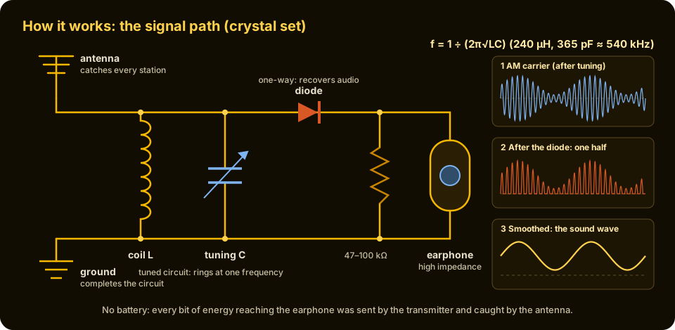
The signal path. The antenna and ground collect a weak mixture of every station in range. The coil and variable capacitor resonate at one frequency, f = 1/(2π√LC), and pass that station on. The diode lets current through in one direction only, which recovers the audio, and the high-impedance earphone turns that audio into sound.
Why keep this in the Knowledge Ark
A crystal radio teaches more about electricity than almost any other single project. It shows that radio waves are real and carry energy, that a coil and a capacitor together form a circuit that "rings" at one frequency, that some materials let current flow one way but not the other, and that sound can ride on an invisible carrier wave. It is also practical. When the power grid fails, broadcast stations and emergency services usually keep transmitting on backup generators, and a receiver that needs no batteries can still hear them. During the Second World War, soldiers and prisoners built crude versions from razor blades, pencil leads and scrap wire. The same knowledge leads directly to the semiconductor diode and the transistor, the building blocks of every modern computer.
History: how it came about
1865: light and radio are the same thing
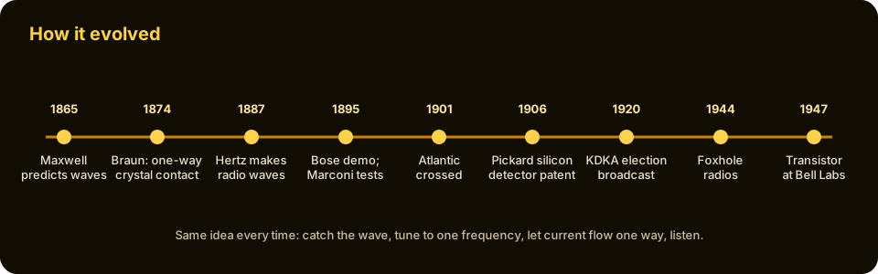
The story starts with a theory, not a machine. In 1865 the Scottish physicist James Clerk Maxwell published A Dynamical Theory of the Electromagnetic Field. His equations tied electricity and magnetism together and predicted that a changing electric current should send out waves of electric and magnetic force travelling through space at the speed of light. Maxwell concluded that light itself is such a wave. If he was right, there should be other, invisible electromagnetic waves too, with wavelengths far longer than light. For more than twenty years no one could make or detect them.
1874: Braun finds the one-way contact
In 1874 the German physicist Karl Ferdinand Braun, then a young researcher, noticed something odd about certain metal sulfide crystals. When he pressed a fine metal point against them, electric current flowed more easily in one direction than in the other. He had found rectification at a point contact between a metal and what we now call a semiconductor. For decades it was a curiosity with no use and no explanation. It would become the "crystal" in the crystal radio.
1887: Hertz makes the waves
Between 1886 and 1888 the German physicist Heinrich Hertz, working at Karlsruhe, proved Maxwell right. He built a spark-gap transmitter: two metal rods with a small gap, charged by an induction coil until a spark jumped across, sending a burst of oscillating current through the rods. A few metres away, a simple loop of wire with its own tiny gap produced a faint spark at the same moment. He showed that these waves could be reflected, focused and polarised just like light, and measured their wavelength. The unit of frequency, the hertz, is named after him. Hertz himself did not foresee practical uses; others soon did.
1890s: detecting the waves
To send messages, a receiver needed a better detector than a spark watched in a darkened room. In 1890 the French physicist Édouard Branly found that a tube of loose metal filings conducted poorly until struck by radio waves, then suddenly conducted well. In 1894 the English physicist Oliver Lodge improved this device and named it the coherer. It was slow and needed tapping to reset, but it worked well enough for Morse code.
In the same years, the Indian physicist Jagadish Chandra Bose in Calcutta was experimenting with very short radio waves, only millimetres to centimetres long, and in 1895 he gave a public demonstration in Calcutta in which, by contemporary accounts, the waves rang a bell and set off a small charge of gunpowder at a distance, through walls. Bose built many detectors, and he became one of the first people to use a semiconductor crystal (galena, a lead sulfide mineral) with a point contact as a radio detector. He applied for a United States patent on a detector for electrical disturbances in 1901; it was granted in 1904. Bose chose not to profit from most of his discoveries, but his work is now recognised as an early root of semiconductor electronics.
1895–1901: Marconi sends messages
The young Italian inventor Guglielmo Marconi set out to turn these laboratory waves into a communication system. In 1895, at his family's estate near Bologna, he found that raising one side of his transmitter high on a pole and connecting the other side to the ground greatly increased the range. The antenna and the earth connection, both still used on this sheet, became the heart of practical radio. He moved to Britain and was granted a British patent in 1897. In 1897 he sent signals across the Bristol Channel, in 1899 across the English Channel, and on 12 December 1901 he reported receiving the Morse letter "S", three short dots, at Signal Hill in St John's, Newfoundland, sent from Poldhu in Cornwall, across the Atlantic Ocean. Marconi and Ferdinand Braun, whose improvements included better tuned transmitter circuits, shared the Nobel Prize in Physics in 1909.
1906: the crystal detector arrives
The coherer could only signal "on" or "off". To hear speech or music, a receiver needed a detector that followed the rise and fall of the signal smoothly. Point-contact crystal detectors did exactly that. The American engineer Greenleaf Whittier Pickard tested thousands of minerals and was granted a patent on a silicon point-contact detector on 20 November 1906. In the same year Henry Harrison Chase Dunwoody patented a detector using carborundum (silicon carbide). Other users favoured galena with a thin springy wire touching it, nicknamed the "cat's whisker". The listener moved the whisker around the crystal surface hunting for a "sensitive spot" that worked best. With these detectors, a radio receiver needed no power source at all.
1920s: the crystal set in every home
Regular public broadcasting began around 1920. The American station KDKA in Pittsburgh broadcast the results of the presidential election on 2 November 1920, and the British Broadcasting Company began transmitting in 1922. In those early years most listeners could not afford valve (vacuum tube) receivers, which needed costly batteries. Crystal sets were cheap, and many were home-made from kits or from instructions printed in magazines. Families shared headphones, sometimes placing a pair in a bowl to make the sound a little louder. As valve and later mains-powered radios became affordable through the late 1920s and 1930s, crystal sets faded, but they remained a favourite first project for young experimenters.
1940s: foxhole radios
During the Second World War, soldiers on the front lines, including Allied troops in Italy around 1944, built improvised receivers called foxhole radios. They used a blued or rusty razor blade as the crystal and a pencil lead or safety pin as the contact, a coil wound on a cardboard tube or a piece of wood, and a headphone from a field telephone. These sets were valued because they gave off no signal of their own, unlike valve receivers whose internal oscillators could leak radio energy. Prisoners of war built similar sets in secret. They prove that a working radio can be made from almost nothing.
From crystals to transistors
Research into crystal detectors during the war, especially silicon and germanium detectors for radar, gave engineers a much better understanding of semiconductors. After the war, sealed germanium point-contact diodes, such as the widely used 1N34, replaced the fiddly cat's whisker. At Bell Laboratories in December 1947, John Bardeen and Walter Brattain, working in a group led by William Shockley, demonstrated the first transistor, itself a point-contact device on a germanium crystal. The three shared the Nobel Prize in Physics in 1956. Every chip in every phone and computer descends from that line of work.
How it works
Radio waves and the carrier
A broadcast transmitter drives a powerful alternating current up and down a tall antenna mast, millions or hundreds of thousands of times a second. That current sends out a radio wave at a fixed frequency called the carrier. Medium-wave (AM) broadcast stations use carriers between about 530 and 1,700 kilohertz in the Americas and about 531 to 1,602 kilohertz in most of the rest of the world. One kilohertz is one thousand cycles per second.
The carrier alone carries no sound. In amplitude modulation, the transmitter makes the carrier's strength rise and fall in step with the sound from the studio microphone. Loud and soft passages, high and low notes, all become changes in the height of the carrier wave. The outline traced by the peaks of the carrier, called the envelope, has the same shape as the original sound wave.
Antenna and ground: catching the energy
When the radio wave passes the receiving antenna, it pushes electrons back and forth in the wire, producing a tiny alternating current at the same frequency. The longer and higher the antenna, the more energy it catches. The ground connection gives that current somewhere to flow to, completing the circuit through the earth. Together they collect a weak mixture of every station within range, each at its own frequency. The power available is extremely small, often measured in millionths of a watt, which is why everything else in the set must waste as little of it as possible.
The tuned circuit: choosing one station
A coil of wire (an inductor, with inductance L, measured in henries) and a capacitor (with capacitance C, measured in farads) connected together form a tuned circuit, also called a tank circuit or LC circuit. Energy sloshes back and forth between the magnetic field of the coil and the electric field of the capacitor, like a child on a swing. Such a circuit responds strongly to one frequency only, its resonant frequency:
f = 1 ÷ (2π × √(L × C))
For example, a coil of 240 microhenries with a variable capacitor set to 365 picofarads resonates at about 540 kilohertz, near the bottom of the medium-wave band. With the same coil and the capacitor turned down to about 40 picofarads (including the small stray capacitance of the wiring), it resonates at about 1,600 kilohertz, near the top. Turning the capacitor's knob therefore sweeps the radio across the band. At resonance the tuned circuit builds up a much larger voltage from the chosen station than from all the others, which it largely shorts away. How sharply it separates stations is called selectivity, and it depends on how little energy the coil, capacitor, antenna and earphone waste.
The detector: recovering the sound
The voltage across the tuned circuit is still a fast radio-frequency wave, far too fast for any earphone or ear to follow. Its positive and negative halves are equal, so on average it pushes nowhere. The detector, a crystal point contact or a modern diode, lets current through in one direction only. It chops off one half of each cycle. What remains is a train of pulses whose average follows the envelope, which is the audio. A small capacitor across the earphone (or the earphone's own capacitance) smooths away the remaining radio-frequency ripple, leaving the sound wave.
The detector must switch on at very low voltages, because the signal is so weak. A germanium diode starts conducting at roughly 0.2 to 0.3 volts, much lower than an ordinary silicon diode at about 0.6 to 0.7 volts. That is why germanium diodes, or certain low-voltage Schottky diodes, are preferred, and why a good galena crystal with a well-placed cat's whisker can also work well.
The earphone: turning current into sound
The audio current from the detector is tiny. An ordinary modern headphone, with an impedance of about 32 ohms, needs more current than the set can supply and stays almost silent. A crystal radio needs a high-impedance earphone, which turns a small voltage into sound without drawing much current. Two kinds work well: piezoelectric "crystal" earpieces, in which a thin crystal disc flexes when a voltage is applied; and old-style magnetic headphones of about 2,000 ohms or more, wound with many turns of very fine wire. A piezoelectric earpiece blocks direct current, so a resistor of roughly 47 to 100 kilohms placed across it lets the detector's output current flow and keeps the detector working properly.
Why no battery is needed
Every bit of energy that reaches the earphone came from the transmitter, travelled through the air as a radio wave and was caught by the antenna. The set simply selects, rectifies and delivers that energy. This is also its limit: it cannot make a weak station louder, only make the best use of what arrives. Strong local stations, a long high antenna and a good ground make the biggest difference.
Parts and what each one does
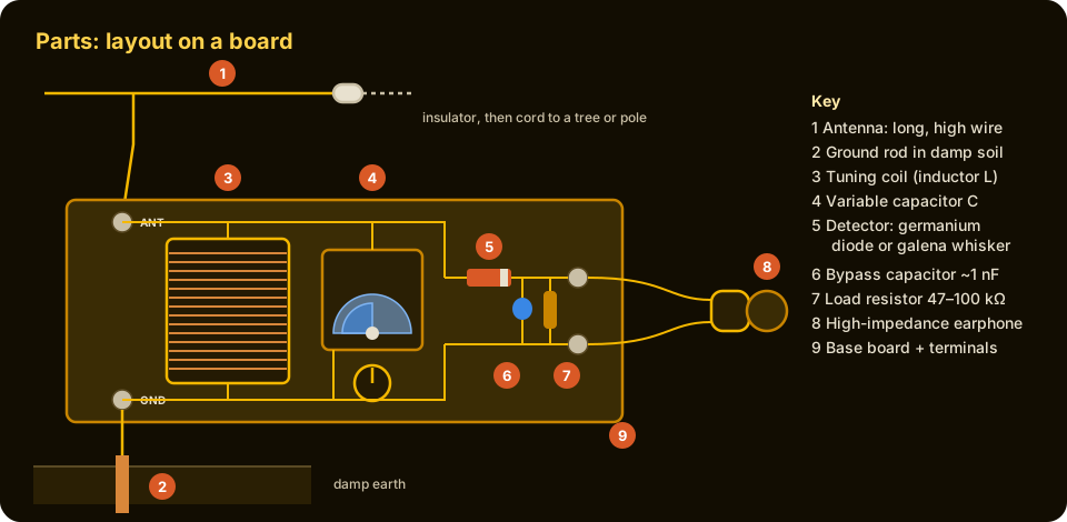
- Antenna. A long bare or insulated copper wire strung as high as possible between insulators. It collects energy from passing radio waves. More length and height means a louder signal.
- Ground (earth) connection. A copper or galvanised rod driven into damp soil, or a clamp on a buried metal water pipe. It completes the circuit. A poor ground is one of the most common reasons a crystal set is weak.
- Tuning coil. Insulated wire wound in a neat single layer on a tube. It provides the inductance of the tuned circuit. Taps (bare loops brought out every so many turns) let the antenna connect partway up the coil, which can sharpen tuning.
- Variable capacitor. Interleaved metal plates, one set fixed and one set turning on a shaft, separated by air or thin plastic. Turning the knob changes how much the plates overlap, changing capacitance and so selecting the station.
- Detector. A germanium diode such as a 1N34A, or a galena crystal with a cat's whisker. It lets current flow one way only and recovers the audio from the carrier.
- Bypass capacitor (optional). A small fixed capacitor, roughly 1,000 picofarads, across the earphone terminals. It smooths away the leftover radio-frequency ripple.
- Load resistor. About 47 to 100 kilohms across a piezoelectric earpiece. It gives the detector's direct current a path and stops the earpiece charging up and going quiet.
- High-impedance earphone. A piezoelectric earpiece or high-impedance magnetic headphones. It turns tiny audio currents into sound.
- Base board and terminals. A dry wooden board with screw terminals or clips. It holds everything in place and makes it easy to try different connections.
Build it: a medium-wave crystal radio
This build makes a basic crystal radio covering most of the medium-wave (AM) broadcast band. Within about 30 to 50 kilometres of a strong AM transmitter, with a good antenna and ground, it should receive at least one station clearly. Farther away, results depend on antenna size, station power and time of day; medium-wave signals travel much farther at night.
Materials
- Tuning coil wire: about 20 to 30 metres of enamelled copper "magnet wire" around 0.3 to 0.5 mm diameter (roughly 24 to 28 AWG), or thin insulated hook-up wire.
- Coil former: a rigid cardboard or plastic tube. A 60 mm diameter tube needs about 60 close-wound turns of 0.4 mm wire for roughly 240 microhenries; a 45 mm cardboard tube needs about 85 turns. The coil can always be adjusted later.
- Variable capacitor: a single-gang tuning capacitor of about 365 picofarads maximum, salvaged from an old valve or transistor radio or bought new. Small plastic transistor-radio "polyvaricon" capacitors also work; use their largest section, or wire two sections in parallel.
- Detector: a germanium diode such as a 1N34A or OA90/OA91, or a low-voltage Schottky diode. Alternatively, a galena crystal with a fine phosphor-bronze or steel cat's whisker.
- Earphone: a piezoelectric (crystal) earpiece or high-impedance magnetic headphones (2,000 ohms or more). Ordinary modern headphones will not work well without a matching transformer.
- Resistor: one of about 47 to 100 kilohms, for use with a piezoelectric earpiece.
- Capacitor (optional): one ceramic capacitor of about 1,000 picofarads (1 nF).
- Antenna wire: 15 to 30 metres or more of copper wire, with two or more plastic or ceramic insulators and strong cord.
- Ground: a copper or copper-clad rod or metal stake at least a metre long, or a clamp for a metal water pipe, plus wire to reach it.
- A dry wooden board, screw terminals or brass screws and washers, a knob for the capacitor, glue, tape and sandpaper.
Tools
Wire cutters, fine sandpaper or a knife to remove enamel from wire ends, small screwdriver, a soldering iron and solder (optional but helpful), a hammer for the ground rod, a ruler and a pencil.
Step 1: wind the tuning coil
Make two small holes near one end of the tube and thread the wire through them to anchor it, leaving about 30 cm free. Wind the wire tightly side by side in a single layer, turn after turn, with no gaps or overlaps. If you want taps, every 10 turns twist a small loop of wire about 2 cm long, then continue winding in the same direction. When the winding is complete, anchor the end through two more holes and leave another 30 cm free. Count and write down the total turns. A coat of varnish or tape keeps the turns in place.
Step 2: prepare the wire ends
Enamelled wire is insulated by a thin varnish that looks like bare copper. Scrape or sand about 1 cm of enamel off every end and tap loop until the wire is bright copper all round. Unclean ends are the most common reason a first crystal set stays silent.
Step 3: mount the parts on the board
Fix the coil to the board with glue or a strap. Mount the variable capacitor at the front edge so its shaft can take a knob. Put in screw terminals labelled ANTENNA, GROUND and two for the EARPHONE.
Step 4: wire the tuned circuit
Connect the top end of the coil to the ANTENNA terminal and to one side (the fixed plates) of the variable capacitor. Connect the bottom end of the coil to the GROUND terminal and to the other side (the moving plates, usually connected to the shaft and frame) of the capacitor. The coil and capacitor are now in parallel, forming the tuned circuit, with the antenna at the top and the ground at the bottom.
Step 5: add the detector and earphone
Connect one end of the diode to the top of the tuned circuit (the ANTENNA side). Connect the other end of the diode to one EARPHONE terminal. Connect the second EARPHONE terminal to the GROUND side. Diodes are marked with a band at one end; for a basic crystal set either way round works, though one may be slightly louder. Put the load resistor across the two EARPHONE terminals, and the optional 1 nF capacitor across them too. Connect the earphone.
Step 6: put up the antenna
Away from power lines, string the antenna wire as high and as long as you can, for example from a tree to the roof or between two poles, with an insulator at each end. Bring a lead-in wire from the near end down to the radio, keeping it away from walls and gutters. An indoor wire along a ceiling will work near a strong station but is much weaker.
Step 7: make the ground
Drive the ground rod into damp soil as close to the radio as practical, ideally where the earth stays moist. Clamp or twist a short heavy wire tightly to it and run it to the GROUND terminal. A metal cold water pipe that runs underground can also serve; check that it is metal all the way, because many modern plumbing runs are plastic. Never use a gas pipe or any part of the electrical wiring.
First signal: test and adjust
- Listen and tune slowly. Put the earphone in, connect antenna and ground, and turn the capacitor knob very slowly from one end to the other. Stations may appear as faint voices or music at one or two settings.
- If you hear nothing. Check every connection for bare, clean copper. Check that the diode is a germanium or Schottky type and is not broken. Try reversing the diode. Try the antenna on a different tap of the coil, or connected directly to the top. Check that the earphone is high-impedance.
- If stations overlap. Move the antenna connection to a tap lower on the coil (fewer turns between antenna and ground), or add a small capacitor of about 100 picofarads in series with the antenna lead. Both reduce how much the antenna loads the tuned circuit, sharpening the tuning at some cost in loudness.
- If the band will not reach the lowest or highest stations. Too few turns means the set cannot tune down to the lowest frequencies: add turns. Too many turns means it cannot reach the highest: remove some. The formula f = 1/(2π√LC) tells you which way to go.
- Using a cat's whisker. With a galena crystal, tune to a station first using a diode, then swap in the crystal and gently move the whisker around the surface until the sound is loudest. Light pressure works best. Vibration or a knock may lose the spot.
- Try at night. Medium-wave signals reflect off the upper atmosphere after dark and can travel hundreds of kilometres, so distant stations often appear in the evening.
Safety
- Lightning is the real danger. A long outdoor antenna can collect a huge charge from a nearby strike or from a storm passing overhead. Never use or touch the set or the antenna during a thunderstorm. When not in use, disconnect the antenna from the radio and connect it directly to the ground rod, outside the building. A lightning arrester or a knife switch outside the house is wise for any permanent antenna.
- Keep well clear of power lines. Never put up an antenna near overhead electrical lines, and never throw a wire or cord over or near one. Contact can kill instantly. Plan the antenna so that if it falls, it cannot touch a power line.
- Never connect any part of a crystal set to mains electricity, mains wiring or a mains earth socket. It needs no power and must never be plugged in.
- Do not use gas pipes as a ground.
- Take care climbing ladders or trees to hang the antenna; have someone hold the ladder. Do not climb in wind or wet weather.
- Soldering irons reach about 300 to 400 °C. Use a stand, work in a ventilated space, wash hands after handling solder (especially older lead solder), and wear eye protection when trimming wire.
- Galena is a lead mineral. Handle it with clean fingers or tweezers, do not grind it or put it near the mouth, and wash hands after use. Keep it away from small children.
- Keep earphone volume in mind: crystal sets are quiet, but a sudden strong signal close to a powerful transmitter can be louder than expected.
Where crystal radio ideas are used now
Few people listen on crystal sets today, but the ideas are everywhere. Every radio, phone, Wi-Fi router and television receiver still uses tuned circuits to pick out one frequency from many. Diode detectors are used in radio-frequency power meters and in simple envelope detectors in AM receivers. Contactless payment cards, building access cards and many shop security tags work like a crystal set in reverse: they have no battery and take all their power from a radio field supplied by the reader, through a coil and a tuned circuit. Radio-frequency identification (RFID) tags, wireless phone chargers and some sensors use the same principle of harvesting energy from a changing field. The transistor, the descendant of the cat's whisker, is in everything electronic.
Words to know
- Amplitude modulation (AM): sending sound by varying the strength of a carrier wave.
- Carrier: the steady radio wave a station transmits, at its assigned frequency.
- Envelope: the outline of the peaks of a modulated carrier, which has the shape of the sound.
- Inductor (coil): a coil of wire that stores energy in a magnetic field; its inductance is measured in henries.
- Capacitor: two conductors separated by an insulator that store energy in an electric field; capacitance is measured in farads.
- Resonant frequency: the one frequency at which a coil and capacitor together respond most strongly.
- Detector: the part that lets current through in one direction only and recovers the sound.
- Diode: a sealed one-way electrical valve, the modern form of the crystal detector.
- Impedance: the total opposition a device offers to an alternating current, in ohms.
Related in the Knowledge Ark
The Knowledge Ark keeps 6,000 packages for rebuilding, from measuring and optics to records and navigation. Browse them, search by category and open any package at the Knowledge Ark. Its sister, the Culture Ark, keeps 2,000 things people should still be able to see in 2,000 years.
Where to learn more
- The IEEE History Center and the Engineering and Technology History Wiki: biographies of Maxwell, Hertz, Marconi, Bose, Braun and Pickard, and IEEE Milestones on early radio.
- The Nobel Prize website: the 1909 physics prize (Marconi and Braun) and the 1956 physics prize (the transistor).
- National Museum of American History and Science Museum Group collections: original crystal sets, cat's whisker detectors and foxhole radios.
- Any introductory electronics textbook covering inductors, capacitors, resonance and diodes.
- Amateur radio organisations, such as national radio societies, for antenna and lightning-protection practice.
Knowledge Ark build sheet. An Artificial Mind Hive (AMH) project. AMH is owned by Austin Little.

Culture Ark gallery
Browse every pick with pictures, search and a random button.
Open the gallery →