Knowledge Ark build sheet · Knowledge Ark · Culture Ark · An Artificial Mind Hive project by Austin Little
A bicycle generator turns the strongest muscles in the human body into electricity. An ordinary bicycle stands in a frame with its back wheel off the ground. The wheel spins a small roller, the roller spins a permanent-magnet motor working backwards as a generator, and the current flows through a one-way diode and a charge controller into a 12-volt battery. From the battery you can run lights, charge phones and radios, or power small tools. This sheet explains where electrical generators came from, how they work, what each part of a pedal-power station does, and how to build one, with honest numbers about how much power a person can really make. Everything here is meant to be rebuilt from scratch if it ever had to be.
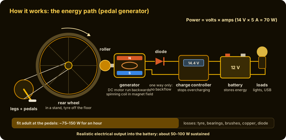
The energy path. Legs turn the rear wheel; the wheel drives a small roller on the generator shaft; spinning magnets and coils inside the generator produce a voltage. A blocking diode stops the battery pushing current back, the charge controller stops it being overcharged, and the battery stores the energy for later use.
Why keep this in the Knowledge Ark
Electricity is the most flexible form of energy people have, and a generator is the machine that makes it. A pedal generator shows, in a way you can feel through your legs, that electrical energy has to come from somewhere: switch on a bigger load and the pedals get harder to turn. It teaches the link between magnetism and current, the difference between power and energy, why batteries need careful charging, and how much work everyday devices really ask for. It is also practical. Where there is no grid, or the grid has failed, a bicycle and a few salvaged parts can keep lights, radios, phones and small medical or communication devices running. Bicycles are among the most common machines on Earth, and so are the small motors that can be turned into generators.
History: how it came about
Before induction
By 1800 people knew a great deal about static electricity, and Alessandro Volta's pile of zinc and copper discs, announced that year, gave the first steady electric current from chemistry. In 1820 the Danish physicist Hans Christian Ørsted noticed that a wire carrying current deflected a compass needle: electricity could make magnetism. Many experimenters then asked the obvious question in reverse. Could magnetism make electricity?
1831: Faraday discovers induction
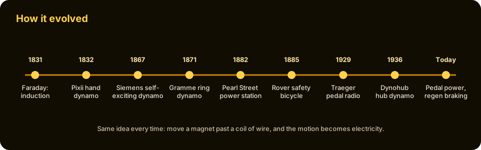
The English scientist Michael Faraday answered it in 1831. On 29 August he wound two coils of wire on opposite sides of an iron ring. When he connected or disconnected a battery to one coil, a needle connected to the other coil jumped, but only at the moment the current changed, not while it stayed steady. In the following weeks he showed that pushing a bar magnet into a coil, or pulling it out, produced a current, and that a copper disc spun between the poles of a magnet gave a continuous current taken off by sliding contacts at its edge and axle. This disc, now called the Faraday disc, was the first electrical generator. The American scientist Joseph Henry made similar discoveries independently at about the same time. The rule they found is that a voltage appears whenever the magnetic field through a circuit changes.
1832: the first dynamos
In 1832 the Paris instrument maker Hippolyte Pixii built a hand-cranked machine in which a horseshoe magnet spun beside two coils. It produced alternating current, flowing first one way and then the other. At the suggestion of André-Marie Ampère, Pixii added a rotating switch, the commutator, that reversed the connections every half turn so the output always flowed in one direction. That is the arrangement inside the brushed motor this build uses. In 1834 the Russian physicist Emil Lenz stated the rule now called Lenz's law: the induced current always flows in a direction that opposes the change that caused it. That is why a loaded generator is harder to turn.
1866–1871: self-exciting dynamos and the Gramme machine
Early generators used permanent magnets, which were weak. Around 1866 and 1867 Werner von Siemens in Germany, and Charles Wheatstone and Samuel Alfred Varley in England, each showed that a generator could feed part of its own output to electromagnets, strengthening its own field as it ran. Siemens called this the dynamo-electric principle, and "dynamo" became the word for a direct-current generator. In 1871 the Belgian engineer Zénobe Gramme built a ring-armature dynamo that gave a much smoother and stronger current, and Gramme machines became the first generators used widely in industry. At the Vienna exhibition of 1873 it was demonstrated that a Gramme dynamo supplied with current would run as a motor. A motor and a generator are the same machine run in opposite directions, which is the idea at the centre of this build.
1882: power stations
On 4 September 1882 Thomas Edison's Pearl Street Station in New York began supplying direct current from large steam-driven dynamos to customers in lower Manhattan. Within a few years alternating-current systems, promoted by George Westinghouse and using inventions by Nikola Tesla and others, proved better for sending power long distances. Alternators driven by steam turbines, water turbines and later wind turbines now produce almost all the world's electricity, all on Faraday's principle.
The bicycle and its lights
The bicycle grew up alongside the dynamo. Karl Drais's two-wheeled running machine appeared in 1817, pedal-driven velocipedes in the 1860s, and John Kemp Starley's Rover "safety bicycle" of 1885, with a chain-driven rear wheel and two wheels of similar size, set the shape bicycles still have. Early bicycle lamps burned oil and then acetylene gas. Small generators driven by the bicycle itself followed. The bottle dynamo, shaped like a small bottle with a ridged wheel pressed against the tyre's sidewall, became common in the first half of the twentieth century. In 1936 the British company Sturmey-Archer introduced the Dynohub, a generator built into the front wheel's hub. Modern hub dynamos, such as those in many European city bikes, are efficient and almost silent; German road rules have long required bicycle dynamos to supply about 6 volts and 3 watts for lighting.
1929: pedal radios in the outback
One of the most important uses of pedal power came in Australia. In the 1920s the engineer Alfred Traeger of Adelaide worked with the Reverend John Flynn and the Australian Inland Mission to bring radio to isolated cattle stations. Traeger designed a transceiver powered by a generator driven by bicycle-style pedals under the operator's table. Introduced in 1929, these pedal radios let families hundreds of kilometres from the nearest town call the new aerial medical service, later the Royal Flying Doctor Service, and later carried lessons for children through the School of the Air. Pedalling for a few minutes could summon a doctor by aeroplane.
Pedal power today
Today pedal generators are used in schools and science centres to show how much energy appliances use, at festivals to power sound systems, in off-grid communities and disaster relief, and by people who want to see the cost of electricity in their own sweat. Hand-crank and pedal chargers for phones and radios are sold for emergency kits. Exercise bikes in some gyms feed electricity back into the building, though the amounts are small compared with the building's needs.
How it works
Induction: moving magnets make voltage
Inside a generator, coils of wire and magnets move relative to each other. As the magnetic field passing through a coil changes, a voltage appears across its ends. The faster the change, the higher the voltage. Spin a generator twice as fast and it makes roughly twice the voltage. More turns of wire, stronger magnets and faster spinning all give more voltage.
A DC motor run backwards
A permanent-magnet brushed DC motor, the kind found in treadmills, cordless drills, car windscreen wipers, scooters and wheelchairs, has fixed magnets around the outside and a spinning set of coils (the armature) inside. Carbon brushes rub on the commutator, which switches the coil connections every fraction of a turn. Feed it current and it spins. Spin it yourself and it produces a direct-current voltage at its terminals, in proportion to its speed. Motor makers often give a rating such as "24 V at 3,000 rpm"; spun as a generator at about 3,000 rpm with no load, that motor gives roughly 24 volts, and at 1,500 rpm roughly 12 volts. This is why the choice of motor and roller size matters so much: the generator has to reach a high enough voltage to charge the battery at a comfortable pedalling speed.
Voltage, current, power and energy
- Voltage (volts, V) is the electrical "push".
- Current (amperes, A) is the rate of flow of charge.
- Power (watts, W) is how fast energy is delivered: power = voltage × current. Charging a 12-volt battery at 5 amperes takes about 60 to 70 watts, because the charging voltage is around 13 to 14.5 volts.
- Energy (watt-hours, Wh) is power multiplied by time. Seventy-five watts for one hour is 75 watt-hours.
Why it gets harder to pedal
When current flows from the generator, that current flowing through its coils in the magnetic field produces a force that pushes back against the spinning, as Lenz's law says. With no load, the generator spins freely. Connect a battery that is accepting a lot of current, and the pedals suddenly feel heavy. The rider is not imagining it: every watt delivered comes from the legs, plus extra for the losses.
How much power a person can make
Here honest numbers matter. A fit, healthy adult can usually keep up roughly 75 to 150 watts of mechanical power at the pedals for an hour; trained racing cyclists hold well over 250 watts, and anyone can produce several hundred watts for a few seconds. Some of that is lost in the tyre rubbing on the roller, in the generator's bearings, brushes and copper windings, in the diode and in the battery itself. A realistic expectation for a well-built home pedal generator is about 50 to 100 watts of electrical output sustained by a fit adult, and less for a beginner, a child or an older person.
An hour of steady pedalling therefore puts roughly 50 to 100 watt-hours into a battery. That is enough to charge a typical smartphone (about 10 to 20 watt-hours of battery) several times, to run a 5-watt LED lamp for 10 to 20 hours, or to run a small radio for days. It is not enough to run an electric heater, kettle, oven or air conditioner, each of which needs 1,000 watts or more; a person cannot produce that for more than a moment. Pedal power is for small, important loads.
Why a battery
People cannot pedal at a perfectly steady rate, and most of the time electricity is needed when no one is pedalling. The battery smooths the uneven supply and stores energy for later. Its voltage stays fairly steady, around 12 to 13 volts, while it charges and discharges, so 12-volt lights, radios and USB chargers can run directly from it.
Why a blocking diode
When the rider stops, the generator's voltage falls below the battery's. Without anything in the way, the battery would push current back into the generator and run it as a motor, spinning the wheel and draining the battery. A diode lets current through in one direction only, so charge can go into the battery but not come back out through the generator. A Schottky diode loses only about 0.3 to 0.5 volts, less than an ordinary silicon diode.
Why a charge controller
A battery can be damaged by being charged too far. A 12-volt lead-acid battery is full at a charging voltage of roughly 14.4 to 14.7 volts; held above that, it overheats, gives off hydrogen and oxygen, and loses water and life. The charge controller watches the battery voltage and cuts back or disconnects the charging current when the battery is full. Most also disconnect loads before the battery is drained too far, which also shortens its life.
Parts and what each one does
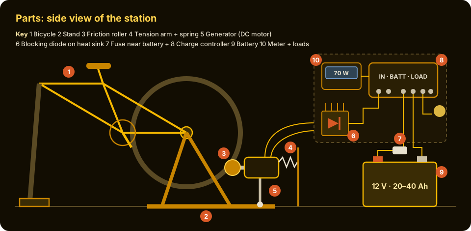
- Bicycle. Any sound bicycle with a working rear wheel and gears. Gears let the rider choose a comfortable cadence while the wheel turns at the speed the generator needs.
- Stand. A frame of wood or steel that holds the rear axle firmly off the ground and keeps the bicycle upright. A commercial "turbo trainer" stand can be adapted.
- Friction roller. A small hard drum on the generator shaft, pressed against the rear tyre. Its diameter sets the gearing between wheel and generator. A belt running on a pulley in place of the tyre (a "tyreless" rim drive) is more efficient but harder to build.
- Tension arm or spring. Holds the generator and roller against the tyre with enough pressure not to slip, and lets it be adjusted.
- Generator. A permanent-magnet brushed DC motor, typically rated 24 volts or more and 200 to 500 watts, used in reverse.
- Blocking diode. A Schottky diode rated at least 15 amperes and 45 volts, on a metal heat sink.
- Fuse. A fuse or circuit breaker close to the battery's positive terminal, to protect the wiring if anything shorts.
- Charge controller. A 12-volt charge controller rated well above the maximum current, for example 20 amperes. A solar charge controller is commonly used.
- Battery. A 12-volt deep-cycle battery, such as a sealed lead-acid (AGM or gel) battery of about 20 to 40 ampere-hours.
- Meters and loads. A voltmeter and ammeter (or a cheap combined watt meter) to show what is happening, plus 12-volt sockets, USB chargers or lamps run from the controller's load terminals.
Build it: a 12-volt pedal generator
This build makes a stationary pedal generator that charges a 12-volt battery at roughly 50 to 100 watts while a fit adult pedals steadily.
Materials
- Bicycle: an ordinary road, hybrid or mountain bike. Smooth road tyres slip less and wear less than knobbly ones.
- Stand: a bike trainer stand, or timber (for example 45 × 90 mm studs), plywood, bolts and a steel plate or block notched to hold the rear axle ends.
- Generator: a permanent-magnet brushed DC motor, preferably rated about 24 to 36 volts and 200 to 500 watts at 2,000 to 3,500 rpm. Treadmill motors and electric scooter motors are common salvage choices. A 12-volt motor is usually a poor choice because it must spin very fast to reach charging voltage.
- Roller: a hard roller about 40 to 60 mm in diameter that fits tightly on the motor shaft, made from aluminium, hardwood, or a short piece of thick-walled pipe pressed onto a shaft coupling. Many treadmill motors come with a flywheel or pulley that can be adapted.
- Blocking diode: a Schottky diode rated at least 15 A and 45 V (for example a 20 A, 45 V or higher device), with a small aluminium heat sink.
- Charge controller: a 12-volt PWM charge controller rated at least 20 A. Check its instructions for which inputs and battery types it accepts.
- Battery: a 12-volt sealed lead-acid deep-cycle battery of 20 to 40 Ah. Small 7 Ah batteries should not be charged at the 4 to 7 amperes a strong rider can deliver.
- Fuse: an inline fuse holder with a 15 to 20 A fuse, to sit within about 20 cm of the battery's positive terminal.
- Wire: at least 2.5 mm² (about 14 AWG) stranded copper wire, red and black, with ring terminals and crimps.
- Meter: a DC voltmeter and ammeter, or a combined DC watt meter rated for the current.
- Loads: a 12-volt socket, a USB charging module and a 12-volt LED lamp.
- Bolts, nuts, washers, a hinge, a strong spring or turnbuckle, cable ties, and an insulated box to hold the electrical parts.
Tools
Spanners, screwdrivers, drill and bits, saw, file, wire strippers, crimping tool, a multimeter, safety glasses and gloves.
Step 1: check the generator and the gearing
Connect a multimeter to the motor's two terminals and spin the shaft by hand or with a drill. A voltage that rises with speed means it will work as a generator. Next, work out the gearing. A typical adult bicycle rear wheel has a circumference of about 2.1 metres. At a road speed of 20 to 25 kilometres per hour, which is a comfortable effort in a middle gear, the tyre surface moves at about 5.5 to 7 metres per second. A 50 mm roller has a circumference of about 0.157 metres, so it would turn about 35 to 44 times a second, roughly 2,100 to 2,700 rpm. A motor rated 24 volts at 3,000 rpm would then give roughly 17 to 21 volts with no load, comfortably above the 14 to 15 volts needed to charge the battery. If your motor's rating is different, choose the roller size to match.
Step 2: build the stand
Build a stand that grips the rear axle on both sides and lifts the rear tyre a few centimetres off the floor. It must not wobble when the rider stands up on the pedals. A wide base, cross-bracing and a front wheel block that keeps the bike level all help. If using a commercial trainer stand, remove its resistance unit.
Step 3: mount the generator
Bolt the motor to a hinged plate or arm on the stand so that the roller sits against the middle of the rear tyre's tread, with the roller's axis exactly parallel to the wheel's axle. Add a spring or adjustable turnbuckle to press the roller against the tyre. Too little pressure and the roller slips and squeals; too much and the tyre wears quickly and pedalling is wasted. Inflate the tyre to its full rated pressure.
Step 4: make the electrical box
Mount the diode on its heat sink, the charge controller, the meter and the fuse holder in an insulated box, away from the spinning wheel. Keep the battery in a separate, ventilated place at floor level, in a battery box or tray.
Step 5: wire it in the right order
- Spin the motor by hand and use the multimeter to find which terminal is positive when the wheel turns in its normal pedalling direction. Mark it.
- Run a red wire from the motor's positive terminal to the diode's anode (the end without the band). The diode's cathode (the end with the band) goes to the positive input of the meter, then on to the charge controller's charging input positive terminal (often marked for a solar panel).
- Run a black wire from the motor's negative terminal to the controller's input negative terminal.
- Connect the battery leads to the controller's battery terminals, with the fuse in the positive lead close to the battery. Most controllers must be connected to the battery first, before the input, so they can detect the battery voltage. Follow the controller's instructions.
- Connect lamps, USB chargers and sockets to the controller's load terminals, so it can switch them off before the battery runs flat.
Step 6: guard the moving parts
Fit a simple guard of plywood or sheet metal over the roller and the part of the tyre near it, so that fingers, hair, clothing and shoelaces cannot be drawn into the gap. Cover the chain and chainring if children will be near.
First power: test and adjust
- Start with no battery load. With the battery connected through the controller but no loads switched on, pedal gently and watch the meter. The voltage should rise; once it exceeds the battery voltage plus the diode drop, current should start to flow and the pedals will feel heavier.
- Find a sustainable pace. Change gear until you can pedal steadily for 20 to 30 minutes while the meter shows a useful current. For a fit adult, 4 to 7 amperes into a 12-volt battery, about 50 to 100 watts, is a good result.
- If the roller slips. Increase the spring pressure a little, clean the roller and tyre, raise the tyre pressure, or wrap the roller in grip tape.
- If the voltage is too low to charge. The generator is turning too slowly: choose a higher gear, pedal faster, use a smaller roller, or use a motor with a higher rpm rating at a lower voltage.
- If the controller or diode gets hot. Check that both are rated well above the current you are producing, that the diode has a heat sink, and that all connections are tight.
- Stop pedalling and check. With the bike still, the meter should show no current flowing back. If the wheel starts to turn by itself, the diode is missing or faulty: disconnect immediately.
- Keep a log. Write down minutes pedalled, average current and battery voltage. After a few sessions you will know exactly how much a person's effort buys in light and charge.
Safety
- Moving parts can injure. The roller and tyre form a pinch point that can trap fingers, hair, loose clothing, scarves and shoelaces. Fit a guard, tie back hair, and keep children and pets away from the spinning wheel.
- Stability. A stand that tips can throw the rider. Build it wide and solid, and test it before full effort.
- Batteries store a lot of energy. A short circuit across a 12-volt battery can deliver hundreds of amperes, melt tools, burn skin and start a fire. Remove rings and metal watch straps when working near terminals, use insulated tools, fit the fuse close to the battery, and connect the battery last when wiring.
- Lead-acid batteries contain sulfuric acid and give off hydrogen when charging. Charge in a ventilated space, away from sparks and flames, and never smoke nearby. Wear eye protection when handling batteries; if acid touches skin or eyes, rinse with plenty of clean water for at least 15 minutes and get medical help. Recycle old batteries; they contain lead.
- Lithium batteries need their own charger and battery management system. Never connect a raw lithium battery or loose lithium cells to a generator. Damaged or overcharged lithium batteries can catch fire violently.
- Unloaded generators can make high voltages. If the battery is disconnected while pedalling hard, the generator's voltage can rise well above battery level and damage the controller or loads. Do not disconnect the battery while the wheel is spinning.
- Mains voltage kills. If you add an inverter to make 120 or 230 volts, treat its output as dangerous as household mains. Never connect a pedal system to household wiring.
- Know your body. Anyone with heart or other health conditions should check with a doctor before hard exercise. Drink water, pedal in short sessions at first, and stop if dizzy or in pain.
Where generators and pedal power are used now
Every power station, from coal and gas to hydro, nuclear and wind, uses generators that work on Faraday's principle, spinning magnets and coils. Cars use alternators to charge their batteries, and electric and hybrid cars run their motors as generators to recover energy when braking, called regenerative braking. Hub dynamos light bicycles across Europe and Asia. Hand-crank radios and flashlights sit in emergency kits. Pedal generators are used in classrooms and off-grid workshops, and at events to power lights and sound. The pedal generator is a small, personal version of the machine that lights the world.
Words to know
- Electromagnetic induction: the production of a voltage in a circuit when the magnetic field through it changes.
- Generator / dynamo / alternator: a machine that turns motion into electricity; a dynamo gives direct current and an alternator gives alternating current.
- Commutator: a rotating switch that keeps a DC machine's current flowing one way.
- Volt, ampere, watt, watt-hour: units of electrical push, flow, power and energy.
- Ampere-hour (Ah): a battery's charge capacity; 20 Ah at 12 volts is about 240 watt-hours.
- Blocking diode: a one-way valve that stops current flowing back from the battery into the generator.
- Charge controller: a device that stops a battery being overcharged or over-discharged.
- Cadence: how fast the rider turns the pedals, in revolutions per minute.
Related in the Knowledge Ark
The Knowledge Ark keeps 6,000 packages for rebuilding, from measuring and optics to records and navigation. Browse them, search by category and open any package at the Knowledge Ark. Its sister, the Culture Ark, keeps 2,000 things people should still be able to see in 2,000 years.
Where to learn more
- The Royal Institution, London: Michael Faraday's laboratory, notebooks and the history of electromagnetic induction.
- The Science Museum Group and the Deutsches Museum: early dynamos by Pixii, Siemens and Gramme.
- The Royal Flying Doctor Service and the National Museum of Australia: the Traeger pedal radio.
- Battery and charge controller manufacturers' data sheets for charging voltages and current limits.
- Any introductory physics or electrical engineering textbook covering induction, DC machines and batteries.
Knowledge Ark build sheet. An Artificial Mind Hive (AMH) project. AMH is owned by Austin Little.

Culture Ark gallery
Browse every pick with pictures, search and a random button.
Open the gallery →