A high-performance positioning system (HPPS) is a machine that moves a tool, a sensor or a part to a precise place in space, quickly and repeatably. Wikipedia describes it as a type of positioning system built from electromechanical equipment that moves an object in three-dimensional space, with up to six degrees of freedom, using high acceleration, high velocity and a short settling time. These machines sit inside many of the products and factories of modern life. They move silicon wafers under the lenses of chip-making machines, place tiny components on circuit boards, carry probes across parts in measuring machines, and guide wires and cutters in precision machine tools.
Because most of these systems move along straight lines using sliding joints, they are often called Cartesian robots or gantry robots, after the x, y and z axes of Cartesian coordinates. This sets them apart from the familiar jointed industrial robot arm, which moves by rotating its joints.
This article explains what makes a positioning system "high performance," how such systems are built and controlled, where they are used, how their accuracy is measured, and what limits them. It includes worked examples showing how the key numbers fit together. Where a figure comes from a vendor or from an uncited part of Wikipedia rather than from a measured test, the article says so.
What "high performance" means
Any positioning system has to answer three questions: where is the load, how fast can it get somewhere else, and how well does it stop where it should? A high-performance system does all three to a very demanding standard at the same time.
| Property | What it means | Why it matters |
|---|---|---|
| Accuracy | How close the actual position is to the commanded position | A wafer or part must be where the machine thinks it is |
| Repeatability | How closely the system returns to the same position on repeated tries | Many processes depend on consistency more than absolute accuracy |
| Resolution | The smallest step the system can command and detect | Sets the finest adjustment possible |
| Velocity | Top speed of travel | Determines time for long moves |
| Acceleration | How quickly speed can change | Determines time for short moves, which dominate many tasks |
| Settling time | How long the load takes to stop vibrating within tolerance after a move | Often the hidden limit on throughput |
| Bandwidth | How quickly the control system can respond to changes and disturbances | Sets how well the system rejects vibration and follows a path |
| Stiffness | Resistance of the structure and drive to being deflected | Higher stiffness gives higher natural frequencies and better control |
According to Wikipedia, systems driven by linear motors can reach speeds of roughly 3 to 5 metres per second and accelerations of about 5 to 7 g (where 1 g is the acceleration of gravity, about 9.81 m/s²), with accuracy of a micron or better. Wikipedia flags that this section of its article lacks citations, so those figures should be treated as typical claims rather than measured benchmarks. Published figures from a motion-control manufacturer and from the lithography company ASML, given later in this article, broadly support the range.
The six degrees of freedom
A rigid object in space can move in six independent ways, called degrees of freedom:
| Degree of freedom | Type | Common name |
|---|---|---|
| X | Translation (straight-line) | Left–right |
| Y | Translation | Forward–back |
| Z | Translation | Up–down |
| Rotation about X | Rotation | Roll (or pitch, depending on convention) |
| Rotation about Y | Rotation | Pitch (or roll) |
| Rotation about Z | Rotation | Yaw |
A simple positioning stage might control only one of these, for example X. A full HPPS for a lithography machine controls all six, because even a tiny tilt of a wafer would throw its surface out of focus. Even when a stage is designed to move in only one direction, its motion contains small unwanted movements in the other five. Much of precision engineering is about measuring and limiting those unwanted movements.
History
The arrival of linear motors
Most machines before the 1980s moved loads in straight lines by turning a rotary motor and converting its rotation into straight-line motion. The usual converters were lead screws, ball screws, belts, and rack-and-pinion drives. Each conversion step adds friction, backlash (play), wear and flexibility.
A linear motor removes the conversion. It can be thought of as an ordinary rotary electric motor that has been cut open and unrolled flat. The motion-control manufacturer Advanced Motion Controls describes it as "a rotary servo motor unrolled." The magnets lie along a track, and the coils ride on the moving part (or the other way round). Electric current in the coils produces force directly along the line of travel.
Wikipedia credits Anorad Corporation with developing the original high-performance positioning system in the 1980s, after the invention of brushless linear motors. Anorad was founded in 1972 by the engineer Anwar Chitayat, who started it in his basement in Plainview, New York. The company name was an acronym for "Anwar's Own Research and Development." Chitayat held many patents, including one for a flat linear motor, and the semiconductor industry association SEMI recognized his work on the brushless linear motor in 2000. Anorad's own company profile claimed it was the first company to introduce commercial linear servo motors.
Rockwell Automation announced in September 1998 that it would acquire Anorad, then based in Hauppauge, New York, describing it as the world leader in linear-motor-based precision positioning equipment. Anorad made linear servo motors, piezoceramic linear motors, positioning stages, air-bearing systems and servo controllers. According to Wikipedia, Siemens, FANUC and Rockwell Automation expanded the integration of linear motors into machines during the 1990s.
Semiconductor lithography drives the frontier
Since the 1990s, the most demanding positioning systems in the world have been the wafer and reticle stages of photolithography machines, which print the patterns of computer chips. In 2000 ASML brought its TWINSCAN platform to market. It used two wafer stages, so that one wafer could be measured while the other was being exposed. In 2008 ASML's NXT platform raised wafer stage acceleration to up to 5 g using lighter stages and magnetic levitation. ASML now states that its magnetically levitated wafer tables can accelerate at up to 7 g, and its reticle stages at about 15 g.
Timeline
| Date | Event |
|---|---|
| 1972 | Anwar Chitayat founds Anorad Corporation in Plainview, New York |
| 1980s | Anorad develops the original HPPS after the invention of brushless linear motors (per Wikipedia) |
| 1990s | Siemens, FANUC and Rockwell Automation expand linear-motor integration |
| 1998 | Rockwell Automation acquires Anorad |
| 2000 | ASML introduces the dual-stage TWINSCAN platform; SEMI recognizes Chitayat's brushless linear motor work |
| 2008 | ASML's NXT platform raises wafer-stage acceleration to up to 5 g |
| 2014 | Current edition of the ISO 230-2 positioning accuracy test code published |
| Today | ASML states wafer tables reach up to 7 g and reticle stages about 15 g |
How an HPPS is built
The main parts
A high-performance positioning system typically contains:
- A base or frame. A heavy, stiff and thermally stable structure that everything else rests on. Materials include granite, cast iron, steel, aluminium and ceramics.
- Guides or bearings. These constrain the moving part so that it travels only in the intended direction. Options include rolling-element linear guides, air bearings (which float the moving part on a thin film of pressurized air), magnetic levitation, and flexures (thin, flexible metal parts that bend instead of sliding).
- Actuators. The motors that create force. In an HPPS these are often linear motors, but ball screws, voice-coil actuators and piezoelectric actuators are also used.
- Position sensors. Linear encoders (precise scales read by an optical or magnetic head), or laser interferometers for the highest accuracy.
- Controller and amplifiers. Electronics that compare the measured position with the commanded position and adjust the motor current many thousands of times per second.
- Cable management and services. Carriers that guide power, signal cables and air or cooling lines to the moving parts without dragging on them.
Common configurations
Wikipedia lists the common configurations as:
| Configuration | Description | Typical use |
|---|---|---|
| Single axis (X) | One straight-line axis | Simple transfer, inspection, as a building block |
| XYZ | Three stacked or combined linear axes | General-purpose assembly and dispensing |
| XYZ plus rotary axes | Adds rotation (for example about Z) | Orienting parts or tools |
| Gantry | A bridge carried on two parallel axes, with a carriage moving along the bridge | Large work areas, pick-and-place, CMMs |
| Custom | Designed for one application | Lithography stages, special machines |
A gantry design is particularly common because it covers a large rectangular area with a light moving bridge. Its challenge is keeping the two sides of the bridge moving in perfect step. If one side leads the other, the bridge twists, a problem known as racking.
Choosing the bearings
The bearing choice shapes how a stage behaves almost as much as the motor choice does.
| Bearing type | How it works | Strengths | Weaknesses |
|---|---|---|---|
| Rolling-element linear guides | Balls or rollers circulate between a rail and a carriage | Stiff, compact, carry heavy loads, relatively low cost | Some friction and small vibrations as the rolling elements recirculate; wear over time |
| Air bearings | A thin film of pressurized air separates the moving part from a precisely flat guide surface | Almost no friction, no wear, very smooth motion | Need clean, dry compressed air and very flat guide surfaces; lower load capacity |
| Magnetic levitation | Magnetic fields hold the moving part with no contact | No friction or wear; works in vacuum; bearing and drive can be combined | Complex control, since the system must actively hold every degree of freedom |
| Flexures | A thin, elastic metal section bends to allow small motions | No friction, no backlash, perfectly repeatable | Only very short travel |
Air bearings are common in coordinate-measuring machines and precision inspection stages because their smoothness makes very small, steady motions possible. Flexures are often combined with piezoelectric actuators for nanometre-scale fine positioning, on top of a coarse stage that covers the long distances.
Sliding joints versus rotating joints
The defining mechanical feature of a Cartesian HPPS is that it uses sliding (prismatic) joints rather than rotating (revolute) joints. This matters for stiffness and accuracy.
In a jointed robot arm, the joints are connected in series: the shoulder carries the elbow, which carries the wrist, which carries the tool. Small angular errors and flexing at each joint add up and are magnified by the length of the arm. In a Cartesian system, each axis moves in a straight line on its own guide, and errors do not get multiplied by long lever arms in the same way.
According to Wikipedia, articulated robots have much lower structural stiffness than an HPPS, which makes them suitable for tasks needing repeatability on the order of hundreds of microns, such as welding and palletizing. Articulated arms have other strengths: they can reach around obstacles, take up little floor space for their reach, and orient a tool in almost any direction.
| Feature | Cartesian HPPS | Articulated robot arm |
|---|---|---|
| Joint type | Sliding (prismatic) | Rotating (revolute) |
| Structural stiffness | High | Lower |
| Typical precision class | Microns to sub-micron | Hundreds of microns for typical tasks (per Wikipedia) |
| Work volume | Rectangular, within the frame | Roughly spherical around the base |
| Flexibility of reach | Limited to the frame | High; can reach around obstacles |
| Typical uses | Lithography, SMT, CMMs, machine tools | Welding, painting, palletizing, material handling |
Drives: linear motors and their alternatives
Linear motor versus ball screw
The choice between a linear motor and a rotary motor driving a ball screw is one of the main design decisions in a positioning system. Advanced Motion Controls, a maker of servo drives, publishes this comparison of representative ranges:
| Criterion | Rotary servo + ball screw | Linear (direct-drive) motor |
|---|---|---|
| Motion path | Rotation converted by a ball screw | Direct linear travel, no conversion |
| Peak acceleration | About 2 g typical | Up to about 10 g |
| Top speed | About 0.5–1 m/s | About 5–10 m/s |
| Positioning accuracy | About 3–5 µm practical floor | Submicron |
| Backlash | Removed by a preloaded nut, but lead error remains | None; no contact in the force path |
| Force | Multiplied by the screw; high thrust | Limited by coil current and magnetics |
The same source notes several trade-offs:
- Force. A ball screw multiplies motor torque into large thrust. A linear motor has no gearing, so its continuous force is limited by how much current its coils can carry before they overheat.
- Speed. Long, thin ball screws have a critical rotational speed above which they start to whip, like a skipping rope. That limits the top speed. Linear motors have no rotating shaft and avoid this.
- Inertia. The screw's gearing reduces the load inertia that the motor "sees," which makes it easier to control loads that vary. A linear motor feels the full mass of the load directly, making varying payloads harder to tune.
- Heat. In a linear motor, the coils often ride with the load and can heat temperature-sensitive work. A rotary motor sits at the end of the axis, away from the work.
- Cost. The rotary-plus-screw path is typically cheaper to buy and gives more force per dollar.
Servo bandwidth
Wikipedia states that linear-motor-driven HPPS reach a servo bandwidth of about 30 to 50 Hz, compared with about 10 to 20 Hz for ball screws and 5 to 10 Hz for belt drives. Like the speed figures above, these are uncited in that article.
The idea behind the comparison is sound even if the exact numbers vary from machine to machine. Servo bandwidth is a measure of how quickly the control loop can react. A higher bandwidth means the system can correct errors faster, follow a commanded path more closely and reject outside vibrations better. Bandwidth is limited by the lowest natural frequency (resonance) of the mechanical system between the motor and the position sensor. A belt stretches, a ball screw twists and compresses, and both create low resonances. A linear motor pushes directly on the load, so the main limit becomes the stiffness of the moving structure itself.
Other actuators
- Voice-coil actuators are small linear motors with a limited stroke, used for fast, short, very smooth motions such as focusing.
- Piezoelectric actuators use crystals that change shape slightly when voltage is applied. They give tiny, extremely precise movements, down to nanometres, over short ranges. They are often used for fine adjustment on top of a coarse stage.
- Magnetic levitation combines bearing and drive in one system. The moving part floats on magnetic fields with no physical contact, which removes friction and wear. ASML uses magnetic levitation for its wafer and reticle stages.
Acceleration and speed: published figures
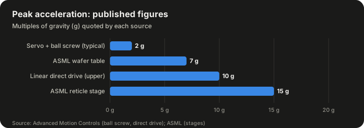
| System | Peak acceleration (g) | Source |
|---|---|---|
| Servo motor + ball screw (typical) | 2 | Advanced Motion Controls |
| ASML wafer table | 7 | ASML |
| Linear direct-drive motor (upper figure) | 10 | Advanced Motion Controls |
| ASML reticle stage | 15 | ASML |
Sources: Advanced Motion Controls, "Linear Motor vs. Rotary Servo Motor"; ASML, "Mechanics and mechatronics."
ASML states that its reticle stage accelerates at up to 150 m/s², about 15 g, and describes that as several times the g-force a fighter pilot feels at take-off. For comparison, an acceleration of 150 m/s² would take a car from 0 to 100 km/h in about 0.19 seconds (100 km/h is 27.8 m/s, and 27.8 ÷ 150 ≈ 0.185 s).
Why acceleration matters more than top speed
In many tasks the moves are short. A pick-and-place machine moves a few centimetres between components. A lithography stage steps from one exposure field to the next. In short moves, the load may never reach top speed at all. The time is dominated by how fast it can speed up and slow down, and by how quickly it settles at the end.
Worked example (hypothetical moves). Compare a 0.5 m move on two machines using a simple "trapezoidal" profile: constant acceleration up to top speed, constant speed, then constant deceleration.
Machine A: linear motor, 5 g (49.05 m/s²), top speed 3 m/s.
- Time to reach top speed: 3 ÷ 49.05 = 0.061 s
- Distance covered while accelerating: 3² ÷ (2 × 49.05) = 0.092 m
- Distance for acceleration plus deceleration: 0.183 m
- Distance at constant speed: 0.5 − 0.183 = 0.317 m, taking 0.317 ÷ 3 = 0.106 s
- Total time: 0.061 + 0.061 + 0.106 ≈ 0.23 s
Machine B: ball screw, 2 g (19.62 m/s²), top speed 1 m/s.
- Time to reach top speed: 1 ÷ 19.62 = 0.051 s
- Distance while accelerating: 1² ÷ (2 × 19.62) = 0.025 m
- Distance for acceleration plus deceleration: 0.051 m
- Distance at constant speed: 0.449 m, taking 0.449 s
- Total time: 0.051 + 0.051 + 0.449 ≈ 0.55 s
Machine A completes the move in well under half the time of Machine B. These numbers are illustrative, chosen from within the published ranges above, and they leave out settling time, which can add significantly to both. In practice, engineers also limit jerk (the rate of change of acceleration) using smoother "S-curve" profiles, because sudden changes in acceleration excite vibrations in the structure.
Control: how the system stays on target
The feedback loop
An HPPS works by feedback. A sensor measures the position. The controller compares it with where the load should be, calculates the error, and changes the motor current to reduce that error. The process repeats continuously. ASML says the position of its wafer stage is measured about 20,000 times per second.
The most common control law is the PID controller, which adjusts the motor force based on the present error (proportional), the accumulated past error (integral) and the rate at which the error is changing (derivative). High-performance systems add more:
- Feedforward control uses knowledge of the planned motion to apply the force needed before an error appears. If the controller knows the load must accelerate at 5 g, it can push with the right force immediately rather than waiting for the position to fall behind.
- Notch filters suppress the controller's response at the frequencies of known structural resonances, so that it does not excite them.
- Disturbance observers and compensation tables correct for repeatable effects such as cable drag, cogging (small force ripples in some motors) and known geometric errors.
Settling time
At the end of a move, the load usually overshoots slightly and oscillates before coming to rest. Settling time is the time it takes for the position error to stay within a specified band. A machine with very high acceleration but a long settling time may be no faster in practice than a gentler machine that stops cleanly. Short settling time requires a stiff structure, well-damped resonances, smooth motion profiles and a well-tuned controller.
Disturbance rejection
Positioning systems must also hold still against outside disturbances: floor vibration, the reaction forces from their own motion, air currents, cable forces and heat. Common strategies include:
- Vibration isolation, mounting the machine on passive springs and dampers or active isolators.
- Reaction masses or balance masses, which move in the opposite direction to the stage so that its reaction force is not passed into the machine frame. ASML notes that its reticle and wafer stages accelerate in opposite directions.
- Stiff, heavy bases of granite or cast iron, which resist being shaken.
- Separate metrology frames, so that the sensors measuring position are mounted on a quiet structure not carrying drive forces.
Accuracy and error sources
Abbe error
One of the most important ideas in precision positioning is the Abbe principle, named after the German physicist Ernst Abbe. Lecture notes from Seoul National University state it as the requirement that the line of measurement (the scale) and the line of the dimension being measured should coincide.
When they do not coincide, any small tilt of the moving part creates a position error. The motion-control company Dover Motion describes Abbe error as a linear error caused by the combination of an underlying angular error and a dimensional offset between the object being measured and the measuring device. The error is approximately:
Abbe error ≈ offset × angle (in radians)
Worked example (hypothetical). Suppose a stage's encoder is 100 mm below the point where a tool works, and the stage pitches by 1 arc-second as it travels. One arc-second is 1/3,600 of a degree, or about 4.85 microradians. The Abbe error is 100 mm × 0.00000485 = 0.000485 mm, or about 0.5 µm. If the tilt were 5 arc-seconds, the error would be about 2.4 µm. If the offset were 1 m, a 1 arc-second tilt would produce about 4.85 µm, which is why some practitioners use a rule of thumb of about 5 µm per metre of offset per arc-second.
In a system designed for sub-micron accuracy, these are large errors. The remedy is to place the sensor in line with the point of interest, keep the offset small, or measure the tilt and correct for it. Lithography stages use laser interferometers aimed directly at the moving table along several axes, partly to satisfy the Abbe principle.
Geometric errors
Every linear axis has errors in each of its six degrees of freedom as it moves:
| Error | Description |
|---|---|
| Positioning (linear) error | Difference between actual and commanded position along the axis |
| Straightness errors (two) | Sideways and vertical deviation from a straight line |
| Pitch, yaw and roll | Small rotations of the carriage as it travels |
A three-axis machine has these six errors on each axis, plus errors in how square the axes are to each other. Precision machines are measured and "mapped," and the controller uses correction tables to compensate for the repeatable part of the errors.
Thermal expansion
Temperature is often the largest source of error in precision machines. Almost every material grows when it warms.
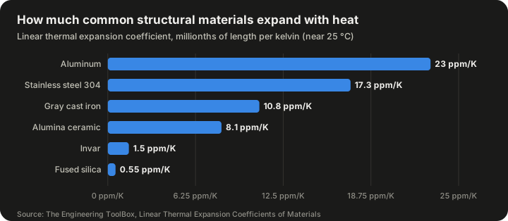
| Material | Linear expansion coefficient (10⁻⁶ per K) |
|---|---|
| Aluminum | 23 |
| Stainless steel, 304 | 17.3 |
| Gray cast iron | 10.8 |
| Alumina ceramic | 8.1 |
| Invar | 1.5 |
| Fused silica | 0.55 |
Source: The Engineering ToolBox, Linear Thermal Expansion Coefficients of Materials (values mostly at 25 °C). The same table gives carbon steel at 10.8–12.5 and granite at 7.9–8.4.
Worked example. A 500 mm aluminium beam warms by just 1 °C. It grows by 500 mm × 23 × 10⁻⁶ = 0.0115 mm, or 11.5 µm. The same beam in gray cast iron grows by about 5.4 µm, in Invar by about 0.75 µm, and in fused silica by about 0.28 µm. For a machine meant to position to a fraction of a micron, a one-degree change in temperature in an aluminium structure would be disastrous.
This is why precision machines use stable materials for critical parts, keep heat sources such as motors away from the work, circulate temperature-controlled fluid, and often operate in climate-controlled rooms. The heat produced by linear motor coils travelling with the load, noted by Advanced Motion Controls, is a particular concern.
Other error sources
- Encoder errors, from imperfections in the scale or its mounting.
- Servo errors, the difference between commanded and actual position caused by limited bandwidth.
- Hysteresis and friction, especially in rolling bearings and screws.
- Load deflection, when the structure bends under the weight or forces of the work.
- Vibration, from the floor, the machine's own motion, or cooling flows.
Measurement and testing
Laser interferometers
A laser interferometer measures distance by counting the interference fringes produced when a laser beam reflected from the moving part is combined with a reference beam. Each fringe corresponds to a fraction of the laser's wavelength, which is well below a micron.
As an example of the capability of commercial instruments, Renishaw's XL-80 laser measurement system is specified at:
| Specification | Value |
|---|---|
| Linear measurement accuracy | ±0.5 ppm (parts per million) over 0–40 °C and 650–1150 mbar |
| Linear resolution | 1 nm |
| Maximum measurement speed | 4 m/s |
| Dynamic capture rate | 50 kHz |
| Standard linear range | 80 m |
An accuracy of ±0.5 ppm means that over a 1 m move, the measurement is good to about ±0.5 µm. This depends on correcting for air temperature, pressure and humidity, which change the speed of light in air and therefore the apparent wavelength. Renishaw achieves this with an environmental compensation unit.
ASML states that the position sensors in its lithography machines are accurate to about 60 picometres, less than the size of a silicon atom.
Autocollimators and frequency response tools
Wikipedia lists autocollimators for measuring angular accuracy (pitch, yaw and roll) and frequency response tools for measuring servo bandwidth. An autocollimator projects a beam of light onto a mirror attached to the moving part and measures tiny changes in the angle of the reflected beam. Frequency response testing shakes the system with signals of varying frequency and records how it responds, revealing resonances and the bandwidth of the control loop.
Standards
The international standard ISO 230-2 is the test code for determining the positioning accuracy and repeatability of numerically controlled axes. Its current edition was published in 2014. It covers both linear and rotary axes and applies when each axis is tested on its own, not when several move at once. It defines quantities such as unidirectional and bidirectional repeatability, the difference being whether the target is approached from one direction or from both. Using a standard test procedure lets buyers compare machines from different makers fairly.
Specifications an engineer writes
When specifying an HPPS, Wikipedia lists the main specifications as: inertia (the mass and its distribution), motion profile, precision, jitter, stiffness, life, reliability and environmental conditions. Typical engineering analyses include dynamics, vibration, accuracy, structural strength, thermal expansion, fluid dynamics (for air bearings and cooling), servo control and reliability.
| Specification area | Example question |
|---|---|
| Inertia | How heavy is the payload, and where is its centre of mass? |
| Motion profile | What moves, over what distances, how often, and with what dwell? |
| Precision | What accuracy, repeatability and resolution are needed? |
| Jitter | How much position noise is acceptable while holding still? |
| Stiffness | How much may the system deflect under process forces? |
| Life and reliability | How many cycles or hours before maintenance? |
| Environment | Clean room, vacuum, temperature range, contamination? |
Applications
Wikipedia lists the following industries and examples:
| Industry | Example application | What the HPPS does |
|---|---|---|
| Semiconductors | Photolithography wafer stages | Moves wafers and masks with nanometre synchronization |
| Electronics assembly | Surface-mount technology (SMT) | Picks components and places them on circuit boards |
| Optics | Stereo microscopes | Positions samples or optics for inspection |
| Machine tools | Wire electrical discharge machining (EDM) | Guides a charged wire that cuts metal |
| Metrology | Coordinate-measuring machines (CMMs) | Carries a probe across a part to measure it |
| Laboratory automation | High-throughput screening | Moves samples and pipettes rapidly between wells |
Photolithography
The most extreme example is the chip-making scanner. A pattern on a mask, called a reticle, is projected through a lens onto a silicon wafer. In a scanning system, the reticle and wafer move at the same time in a precisely coordinated way. ASML says the motion must be synchronized "to the nanometer and nanosecond." The reticle moves faster and farther than the wafer because the pattern on it is larger than the image printed on the wafer, which is why the reticle stage needs the higher acceleration. ASML says its machines can handle up to 275 wafers per hour, with the pattern printed in almost 100 places on each wafer.
Dual-stage designs such as ASML's TWINSCAN let one wafer be measured on one stage while another is exposed on the second, increasing throughput.
Electronics assembly
In surface-mount technology, machines pick tiny components from tape reels and place them on circuit boards. A single machine may place many thousands of components per hour. The moves are short and very frequent, so acceleration and settling time dominate productivity, as shown in the worked example earlier.
Coordinate-measuring machines
A CMM is a positioning system whose job is to measure rather than make. It moves a probe, which may touch the part or measure it optically, across the surface of a manufactured part to check its dimensions. Because its purpose is measurement, a CMM's accuracy is everything. Many use granite bases and air bearings for stability and smooth motion.
Machine tools
In wire EDM, a thin electrically charged wire cuts hard metal by sparking. The wire must follow the programmed path accurately, but the cutting forces are small. This makes it suitable for high-precision linear drives. Other machine tools, such as high-speed milling machines, have also adopted linear motors on some axes.
Laboratory automation
Drug discovery labs test huge numbers of chemical samples in plates with hundreds or thousands of small wells. Automated systems move pipettes, plates and detectors between positions quickly and repeatably, so that large screening experiments can run with little human handling.
Limits and trade-offs
High-performance positioning systems are powerful but not always the right choice.
- Cost. Linear motors, precision encoders, air bearings and stable materials are expensive. A ball-screw stage is often cheaper and sufficient.
- Heat. Fast moves need large forces, and large forces in linear motors mean large currents and heat. Heat brings thermal expansion, which undermines accuracy.
- Force limits. Without gearing, a linear motor's continuous force is limited, so heavy cutting or pressing operations may suit screw drives better.
- Safety and braking. A linear motor axis has no self-locking screw. If power fails, a vertical axis can fall, so brakes or counterbalances are needed. Fast-moving loads also need guarding.
- Magnet attraction and debris. Linear motor magnet tracks attract steel chips and dust, which can be a problem in machining environments.
- Workspace. A Cartesian system's reach is confined to its frame. Tasks that need reaching around obstacles or into confined spaces may suit an articulated arm better.
- Environment. Achieving the best accuracy often needs climate control, vibration isolation and clean conditions, which add cost beyond the machine itself.
Common misconceptions
"Accuracy and repeatability are the same thing." They are not. A machine can return to the same wrong position every time (good repeatability, poor accuracy). Many processes, such as assembly against a vision-measured reference, depend more on repeatability.
"Resolution equals accuracy." An encoder with 1 nm resolution does not make a stage accurate to 1 nm. Thermal growth, Abbe error and guide imperfections can be far larger than the smallest step.
"Top speed determines throughput." For short moves, acceleration and settling time matter far more, as the worked example shows.
"Linear motors are always better than ball screws." Linear motors are faster and avoid backlash, but ball screws give more force per dollar, generate heat away from the work, and handle variable loads more easily.
"Cartesian robots and industrial robot arms are interchangeable." They suit different jobs. Cartesian systems excel at stiffness and precision within a box-shaped space; articulated arms excel at flexible reach.
"A heavier machine is always more accurate." Mass helps resist vibration, but moving parts should be light to allow high acceleration without huge forces. The art is in making the base heavy and stiff and the moving parts light and stiff.
Frequently asked questions
What is a high-performance positioning system? A machine that moves a load to precise positions in space with high acceleration, high speed and short settling time, usually using sliding joints in Cartesian (x, y, z) axes.
Why are they called Cartesian robots? Because they move along straight axes that match the x, y and z directions of Cartesian coordinates, using sliding rather than rotating joints.
What drives them? Often linear motors, though ball screws, voice coils, piezoelectric actuators and magnetic levitation are also used.
How fast can they accelerate? Published figures range from about 2 g for a typical ball-screw stage, to up to about 10 g for linear direct-drive motors according to Advanced Motion Controls, to about 15 g for ASML's reticle stages.
How accurate are they? It depends on the design. Linear-motor stages can reach sub-micron accuracy. Lithography machines measure stage position with sensors that ASML says are accurate to about 60 picometres.
Who invented them? Wikipedia credits Anorad Corporation, founded by Anwar Chitayat, with developing the original HPPS in the 1980s after brushless linear motors were invented.
How is their accuracy checked? With laser interferometers for linear position, autocollimators for angles and frequency response tools for servo bandwidth, often following procedures such as ISO 230-2.
Why does temperature matter so much? Because materials expand when they warm. A 500 mm aluminium part grows by about 11.5 µm for each degree Celsius, which is enormous compared with sub-micron tolerances.
Where are they used? In semiconductor lithography, electronics assembly, optics, machine tools, coordinate-measuring machines and laboratory automation.
Why they matter
High-performance positioning systems are largely invisible to the public, but they make much of modern technology possible. The chips in phones and computers are printed by machines whose stages accelerate faster than a fighter jet and stop with nanometre precision. Circuit boards are populated by gantries making short, fast moves thousands of times an hour. Parts for engines and medical devices are checked by measuring machines that move probes with micron accuracy.
The engineering behind them combines mechanics, electronics, control theory, materials science and measurement. Progress in one area often depends on progress in the others: faster motors need stiffer structures, stiffer structures allow higher control bandwidth, and higher accuracy demands better sensors and better control of heat. That interplay is what makes high-performance positioning a central field of precision engineering and mechatronics.
Sources
- High performance positioning system – Wikipedia
- Advanced Motion Controls: Linear Motor vs. Rotary Servo Motor
- ASML: Mechanics and mechatronics
- Anwar Chitayat – Wikipedia
- EC&M: Rockwell acquisition adds linear motors
- Control Engineering: Linear Motors and Controls Seek the Mainstream
- Bioprocess Online: Anorad Corporation company profile
- Renishaw: XL-80 laser measurement system
- Dover Motion: Abbé Error
- Seoul National University OCW: Design lecture 1, concepts (Abbe principle)
- Machine Design: Tips for choosing high-accuracy linear positioning systems, Part 2
- ISO 230-2:2014 – Test code for machine tools, positioning accuracy and repeatability (EVS listing)
- The Engineering ToolBox: Linear Thermal Expansion Coefficients of Materials