A cover meter is a hand-held instrument that finds steel reinforcing bars (rebar) inside concrete and measures how deep they are below the surface. That depth is called the concrete cover, and it is one of the most important numbers in the life of a reinforced concrete structure. Too little cover and the steel corrodes early, cracking and spalling the concrete around it. Too much cover and cracks open wider than the design intended, and the steel sits further from the surface than the structural calculations assumed.
The instrument goes by several names. In the United States it is often called a covermeter, a pachometer or an R-meter; in Britain, a cover meter. Simpler devices that only find metal, without measuring depth, are usually called rebar locators or rebar detectors. The Wikipedia article on the subject draws exactly this distinction: a rebar detector locates metal objects, while a cover meter also measures the cover.
Cover meters are electromagnetic. They do not see the steel in an optical sense; they generate a magnetic field, detect how the steel disturbs it, and infer position and depth from the disturbance. Because concrete itself is non-magnetic and non-conductive, it is essentially invisible to the instrument. That is the method's great strength, and the reason it has become a routine tool for engineers, inspectors and contractors. It is also the source of its limitations, because any other steel nearby is just as visible as the bar being measured.
This article explains why cover matters, what design codes require, how cover meters work, how measurements are made and checked, what accuracy can realistically be expected, where the method fails, and how it compares with ground-penetrating radar and other techniques.
Why concrete cover matters
Cover defined
The American Concrete Institute's terminology, as quoted in the Wikipedia article on concrete cover, defines it as "the least distance between the surface of embedded reinforcement and the outer surface of the concrete." The word "least" is important: cover is measured to the nearest steel, which is often a stirrup, tie or link rather than the main bar.
Cover does three jobs:
- It protects the steel from corrosion. This is usually the deciding factor.
- It insulates the steel from fire. Steel loses strength at high temperature, and the concrete layer slows the rise in steel temperature.
- It allows the bar to bond to the concrete. A bar needs a minimum surrounding of concrete to transfer force without splitting the concrete around it.
How concrete protects steel
Fresh concrete is strongly alkaline. The Wikipedia article on concrete cover gives the pH of fresh cement pore water as about 13.5, falling to about 12.5 as the cement matures. In this alkaline environment, steel forms a thin passive film that prevents corrosion. As long as the pore water stays above a pH of about 10.5, the steel stays passive.
Two processes break that protection down.
Carbonation. Carbon dioxide from the air diffuses into the concrete and reacts with calcium hydroxide to form calcium carbonate. The Wikipedia article on concrete degradation gives the reaction as CO₂ + Ca(OH)₂ → CaCO₃ + H₂O and notes that carbonation lowers the pore-water pH to about 8.5. Once the carbonation front reaches the steel and the pH drops below roughly 9.5 to 10.5, the passive film is lost and corrosion can start if water and oxygen are present. Carbonation slows as it moves deeper, so a thicker cover buys disproportionately more time. Engineers check carbonation depth by spraying a freshly broken concrete surface with phenolphthalein indicator, which is colourless below about pH 8.5 and pink above about 9.5.
Chlorides. Chloride ions from de-icing salts, seawater or, historically, calcium chloride added to speed setting, break down the passive film locally and cause pitting corrosion. This is particularly dangerous because it is concentrated and hidden: a bar can lose much of its cross-section at a pit before any sign appears on the surface.
Why corrosion cracks concrete
Rust occupies far more volume than the steel it replaces. The concrete degradation article states that iron oxides take up roughly six to seven times the volume of the original iron. This expansion pushes outwards on the surrounding concrete. Concrete is weak in tension, with tensile strength about ten times lower than its compressive strength according to the same source, so the cover cracks and eventually spalls off, exposing the steel and accelerating the damage. The process is often called "oxide jacking."
The Wisconsin Department of Transportation's structure inspection manual summarises the link to cover clearly: if the cover is too shallow, carbonation will reach the steel and the alkaline protection will be lost; exposure to road salts and moisture then accelerates corrosion once the cover is breached by cracks or spalls.
Why too much cover is also a problem
It is tempting to think more cover is always better. It is not. The same WisDOT manual notes that if the cover is too deep, crack widths increase and the effective depth of the member decreases, both of which affect the design. The effective depth (the distance from the compression face to the centre of the tension steel) governs a beam's or slab's bending strength, so a slab with bars placed too low is weaker than designed. The Wikipedia article on concrete cover adds that crack widths above 0.3 mm let in moisture and chemicals, which can lead to corrosion.
So the goal is not maximum cover, but the specified cover, achieved consistently.
What the design codes require
Eurocode 2
In Europe, cover is set by EN 1992-1-1 (Eurocode 2). The method, as laid out in worked examples based on the standard, works in two steps.
First, a minimum cover is found as the largest of three values:
cmin = max { cmin,b ; cmin,dur + Δcdur,γ − Δcdur,st − Δcdur,add ; 10 mm }
where cmin,b is the cover needed for bond (equal to the bar diameter for a single bar), cmin,dur is the cover needed for durability, and the Δ terms are optional adjustments for additional safety, stainless steel and extra protection (all zero in a typical case).
Second, a nominal cover is specified on the drawings by adding an allowance for construction deviations:
cnom = cmin + Δcdev
The recommended value of Δcdev is 10 mm. This allowance is directly relevant to cover meters: it is the tolerance that site placement is expected to stay within, and cover surveys check whether it has.
The durability cover depends on the exposure class, which describes the environment, and the structural class, which reflects design life and concrete quality. For a 50-year design working life, the recommended structural class is S4.
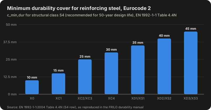
| Exposure class | Environment (summary) | cmin,dur (mm), class S4 |
|---|---|---|
| X0 | No risk of corrosion | 10 |
| XC1 | Carbonation, dry or permanently wet | 15 |
| XC2 / XC3 | Carbonation, wet rarely dry / moderate humidity | 25 |
| XC4 | Carbonation, cyclic wet and dry | 30 |
| XD1 / XS1 | Chlorides, moderate humidity / airborne sea salt | 35 |
| XD2 / XS2 | Chlorides, wet rarely dry / permanently submerged in seawater | 40 |
| XD3 / XS3 | Chlorides, cyclic wet and dry / tidal and splash zones | 45 |
Source: EN 1992-1-1:2004 Table 4.4N, S4 row, as reproduced in the FRILO durability manual. National annexes may change these values.
A worked example (from a published Eurocode calculation)
A published worked example on Eurocode Applied takes a 20 mm bar in exposure class XC4 with a 50-year design life:
- Bond cover: cmin,b = 1.0 × 20 mm = 20 mm
- Durability cover: cmin,dur = 30 mm (S4, XC4)
- Minimum cover: cmin = max {20, 30, 10} = 30 mm
- Nominal cover: cnom = 30 + 10 = 40 mm
The drawing would therefore specify 40 mm. A cover survey on the finished element would be checking that the actual cover does not fall below 30 mm, the minimum the design relies on.
National variations
Eurocode values are "recommended"; each country's national annex can change them. The worked examples note that the French annex allows the structural class to be reduced for some concrete strengths, and the German annex uses a different row of values. Anyone checking cover against a design must use the values for the country and code edition the structure was designed to.
Other codes
The Wikipedia article on concrete cover lists typical minimum cover ranges in several national codes:
| Country | Code | Typical minimum cover range |
|---|---|---|
| United Kingdom | BS 8110 | 25–50 mm |
| European Union | EN 1992 (Eurocode 2) | bar diameter + 10 mm, up to 55 mm |
| United States | ACI 318 | 40–75 mm |
| Australia | AS 3600 | 15–78 mm |
| India | IS 456 (2000) | 20–75 mm |
Source: Wikipedia, "Concrete cover."
In the United States, ACI 318 specifies cover by exposure and member type. Reproductions of the ACI 318-19 table give 3 inches for concrete cast against and permanently in contact with the ground; 2 inches for No. 6 through No. 18 bars, and 1.5 inches for No. 5 bars and smaller, in concrete exposed to weather or in contact with ground; and, for concrete not exposed to weather, 3/4 inch for slab bars No. 11 and smaller and 1.5 inches for beam and column primary reinforcement, stirrups and ties. Designers should check the current edition directly.
How a cover meter works
The basic idea
All cover meters are electromagnetic. As John Alldred of Protovale described in a 1995 paper, a coil in the instrument's search head generates a primary magnetic field that penetrates the concrete. The field interacts with the steel through the steel's magnetic permeability and its electrical conductivity. This interaction produces a secondary field, which is picked up either by a second coil or by the same coil. The signal grows with bar size and falls with increasing cover. The instrument is calibrated on the assumption that there is a single bar in the field.
The WisDOT manual describes it the same way in simpler terms: the device produces a magnetic field and locates the reinforcing steel by measuring the distortion the steel creates. With more than one sensor, the meter can be calibrated to convert the signal into a distance.
Pulse induction
The Wikipedia article identifies pulse induction as one of the most common methods, chosen because it is cost-effective. It works in a sequence:
- Coils in the probe are periodically charged by current pulses, producing a magnetic field.
- When each pulse ends, the collapsing field induces eddy currents in any nearby conductive material, including the steel bar.
- These eddy currents produce their own magnetic field, which opposes the change.
- The instrument measures the resulting voltage in the coil as the field decays.
A bar that is closer, or larger, produces a stronger response. Modern instruments use several coil arrangements and signal processing to locate the bar, determine the cover and estimate the bar's diameter.
Because the measurement depends on conductivity and permeability, non-conductive, non-magnetic materials (concrete, wood, plastic, brick) do not affect it, while any nearby conductive material does.
Why two unknowns make it hard
There is a fundamental ambiguity in any cover meter. A large bar deep down and a small bar near the surface can produce the same signal strength. To measure cover accurately, the meter must know the bar diameter, either because the user enters it from the drawings or because the instrument estimates it.
Instruments estimate diameter in several ways, typically by taking readings with different coil geometries or orientations and comparing them. Protovale's documentation for its CoverMaster CM9 instrument describes two diameter-determination methods, "AutoSize" and "Orthogonal," and states that users should expect diameter accuracy of about ±2½ bar sizes with AutoSize and ±1½ sizes with the orthogonal method. In other words, diameter estimation is markedly less precise than cover measurement, and an error in assumed diameter feeds directly into an error in cover.
What the instrument displays
A typical modern cover meter shows:
- A signal-strength indicator that peaks when the probe is directly over a bar.
- The estimated cover depth, once a bar is located.
- An estimated bar diameter, on instruments that support it.
- Logging of readings, often in a grid or line-scan format that can be exported to produce a cover map.
How a cover survey is carried out
Before going on site
A good survey starts with the drawings: the specified cover, bar sizes and spacing, and the location of laps and congested zones. Knowing the expected bar diameter is essential for accurate cover readings. If drawings are not available, a small number of bars may be exposed by breaking out the concrete to confirm size and depth.
Checking the instrument
The instrument's calibration should be verified before use. BS 1881-204, the British standard on electromagnetic covermeters, describes a test using a prism with a bar at known cover. Protovale's application note on verifying its CM9 refers to the BS 1881-204 prism test, and also describes a quick check at 30 mm cover that requires no spacer and a method for verifying performance around 90 mm. The same note uses a ±2 mm tolerance for its own check at 40 mm cover. A simple user check is to place the probe over a bar through spacers of known thickness made from a non-magnetic material.
Locating the bars
The user sweeps the probe across the surface. When the signal peaks, the probe is directly over a bar, and the bar's direction is found by rotating the probe until the signal is strongest (most probes are directional and give the strongest response when aligned with the bar). Bar positions are marked on the surface, often in chalk. Doing this in two directions reveals the grid of top-layer reinforcement.
Measuring cover
Once a bar is located, the probe is placed over it, aligned with it, and the cover is read. Readings are taken at regular intervals along bars and at locations of concern, such as edges, corners and areas where cracking or rust staining is visible.
Using the results
Individual readings are rarely the end point. Cover surveys usually produce:
- A cover map showing measured depth across the surface.
- A statistical summary, such as mean, minimum and the percentage of readings below the required minimum.
- A comparison against the specified nominal cover and the allowed deviation.
Areas of low cover can then be targeted for further investigation: carbonation depth measurement, chloride testing, half-cell potential surveys or breaking out to inspect the steel.
A worked example: evaluating a small survey (hypothetical)
Suppose an inspector takes ten cover readings along the top bars of a newly cast slab specified with 40 mm nominal cover and a 30 mm minimum, as in the Eurocode example above. The readings, in millimetres, are: 42, 38, 35, 44, 31, 29, 40, 37, 33, 41.
- Mean: the readings sum to 370 mm, so the mean is 370 / 10 = 37 mm.
- Minimum: 29 mm.
- Readings below the 30 mm minimum: one out of ten, or 10%.
- Readings below the 40 mm nominal: six out of ten (38, 35, 31, 29, 37 and 33).
- Spread: the readings range from 29 to 44 mm, a span of 15 mm.
What does this tell the engineer? On average, the slab is 3 mm short of its nominal cover, which is well within the 10 mm deviation allowance the design assumed. One reading falls just below the minimum. But that reading, 29 mm, is only 1 mm below the limit, and under average site conditions the tolerance at that depth is about ±5 mm. The reading is therefore not proof of a defect, but it is a flag. A sensible next step would be to break out at that location to measure the true cover directly, check the bar diameter against the value entered in the meter, and, if the slab will be exposed to carbonation or chlorides, consider whether a protective treatment is warranted for the low-cover zone.
This example also shows why readings should never be judged one at a time. The pattern matters: a single low reading in an otherwise compliant area may reflect a displaced bar or a local chair failure, while a band of low readings along one edge suggests a systematic problem with how the reinforcement was supported during the pour.
Reporting the survey
A useful cover survey report normally records:
- The instrument used, its calibration check and the bar diameter assumed for each area.
- The locations of all readings, tied to drawings or a grid.
- The individual readings and a summary of mean, minimum and percentage below the specified minimum.
- The locations of any break-out or drilled checks and how the direct measurements compared with the meter readings.
- Any conditions likely to affect accuracy, such as congested zones, laps, nearby steel or rough surfaces.
Recording the assumed diameter is especially important. If it later turns out to be wrong, the readings can be corrected; if it was never recorded, the survey may have to be repeated.
Confirming by breaking out
Cover meters are calibrated assumptions, not direct measurements. On any significant survey, a few readings should be checked by drilling or breaking out to expose the bar and measure the cover directly. This also confirms the bar diameter, which improves the accuracy of all the other readings.
How accurate is a cover meter?
What BS 1881-204 says
BS 1881-204:1988, "Testing concrete. Recommendations on the use of electromagnetic covermeters," gives accuracy expectations that depend on conditions. As summarised by Alldred (1995):
- Ideal laboratory conditions, single bar: error should not exceed the greater of ±5% or ±2 mm.
- Favourable site conditions: accuracy should approach laboratory performance (no number given).
- Average site conditions: accuracy is likely to be within the greater of ±15% or ±5 mm.
Alldred also cites a 1984 draft of the standard that proposed ±3 mm at shallow cover, with an interpolated ±8% at deeper cover, and treats these as "desirable" targets rather than requirements. Protovale's CM9 documentation refers to Table 3, row 2, of the standard permitting cover errors of ±5 mm in its relevant check, and notes that the standard sets no requirement for diameter determination.
Because the tolerance is "the greater of" a percentage and a fixed amount, the tolerance grows with depth. The chart below applies the rules arithmetically.
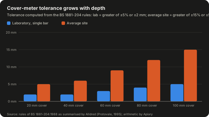
| True cover | Laboratory tolerance (greater of ±5% or ±2 mm) | Average site tolerance (greater of ±15% or ±5 mm) |
|---|---|---|
| 20 mm | ±2 mm | ±5 mm |
| 40 mm | ±2 mm | ±6 mm |
| 60 mm | ±3 mm | ±9 mm |
| 80 mm | ±4 mm | ±12 mm |
| 100 mm | ±5 mm | ±15 mm |
Source: BS 1881-204:1988 rules as summarised by Alldred (Protovale, 1995); tolerances calculated from those rules.
Reading the table in practice (hypothetical)
Consider a slab where the Eurocode calculation above gives a nominal cover of 40 mm and a minimum of 30 mm, a margin of 10 mm. Under average site conditions, a reading at 40 mm cover carries a tolerance of about ±6 mm. A reading of 34 mm could correspond to a true cover anywhere from about 28 mm to 40 mm. So a reading that appears acceptable may not prove compliance, and a reading slightly below 30 mm may not prove non-compliance. This is why surveys rely on many readings and statistical evaluation, and why breaking out a few locations to calibrate the survey is so valuable.
Other published figures
- The WisDOT manual states that covermeters in general can accurately measure cover to within 0.25 inch (about 6 mm) in the range of 0 to 3 inches (about 0 to 76 mm) in lightly reinforced members.
- A 2024 study in the ACI Materials Journal comparing two commercial cover meters with a ground-penetrating radar device found that a cover meter was most accurate for depths smaller than 3.19 inches (81.0 mm), while the radar performed better at greater depths.
- RILEM Technical Committee 189-NEC, which studied non-destructive evaluation of the concrete cover, organised comparative tests of commercial covermeters. The results, reported by L. Fernández Luco in Materials and Structures in 2005, led the committee to conclude that modern covermeters, mostly of the eddy-current type, can locate single bars and estimate cover and diameter with high accuracy, though performance varies between instruments.
- Manufacturer specifications often claim accuracy of ±1 mm to a few millimetres depending on depth. These are measured under ideal single-bar conditions and should be read alongside the site tolerances above.
What makes readings go wrong
Congested reinforcement
This is the biggest single problem. A cover meter assumes one bar. When two or more bars are within its field, the combined signal is stronger, so the meter reports the steel as shallower than it really is. Alldred's 1995 paper, "Quantifying the losses in cover-meter accuracy due to congestion of reinforcement," tested instruments from four manufacturers (James Instruments, Kolectric, Proceq and Protovale) against ribbed high-tensile bars at varying pitch, and found that error at the minimum pitch-to-depth ratio varied widely between instruments and head designs. The broader lesson is that the closer bars are to each other relative to their depth, the less reliable the reading.
The Wikipedia article puts this as a disadvantage of the method: the minimum bar spacing that can be resolved depends on the cover depth. The deeper the bars, the further apart they must be to be resolved separately.
The WisDOT manual adds that the problem is most pronounced in heavily reinforced structures.
Laps and multiple layers
Where bars overlap at a lap splice, two bars sit side by side, which looks like one larger, shallower bar. Where there are two layers (for example, a top mat with bars in both directions), the lower bars add to the signal from the upper ones. A Kentucky Transportation Center project on bridge deck cover verification noted that lapped bars and negative-moment reinforcing steel can affect the accuracy of pachometer measurements.
Other steel
Scaffolding, window frames, embedded plates, conduit, tie wire, nails and form ties all disturb the field. Alldred names metal window frames and scaffolding specifically, and the WisDOT manual names large steel objects such as scaffolds near the test area.
Wrong bar diameter
Because signal strength depends on both depth and size, entering the wrong diameter produces a cover error. If the meter's own diameter estimate is used, its uncertainty (Protovale's documentation gives about ±1½ to ±2½ bar sizes, depending on the method) carries through to the cover estimate.
Epoxy-coated bars
The WisDOT manual notes that some reports indicate epoxy coatings can distort cover meter readings.
Magnetic aggregates and cement
BS 1881-204 lists magnetic effects of the concrete matrix and aggregate as a potential error source. Alldred states that a well-designed meter should be little affected by them, but in concretes with unusual aggregates (for example, some slags or iron-bearing stones) it is worth checking by breaking out.
Surface roughness and probe lift-off
The meter measures from the face of the probe. A rough or uneven surface lifts the probe, adding to the indicated cover. Alldred treats errors comparable to surface roughness and rib height as inconsequential for practical purposes, but on heavily textured surfaces it can matter.
Depth limits
Every instrument has a maximum range, beyond which the signal is too weak. The Wikipedia article lists limited detection range among the disadvantages. Manufacturers' quoted ranges vary considerably and depend on bar size: a large bar is detectable at greater depth than a small one.
What cover meters cannot tell you
Even a perfect cover reading leaves important questions unanswered. The WisDOT manual is explicit that a covermeter only locates the steel and gives no information about defects or the state of deterioration. A cover meter cannot tell you:
- Whether the steel is corroding.
- Whether the concrete is carbonated or contaminated with chloride.
- Whether there are voids, honeycombing or delaminations.
- The strength of the concrete.
For these, other methods are needed, which is why cover surveys are usually one part of a wider condition assessment.
Cover meters compared with other methods
Ground-penetrating radar
Ground-penetrating radar (GPR) sends short pulses of radio energy into the concrete and records reflections from interfaces, including steel bars. It can scan large areas quickly and see deeper than a cover meter, and it can detect non-metallic objects such as plastic ducts and voids. Its disadvantages are that the depth calculation depends on the speed of radio waves in the concrete, which varies with moisture and composition, so it needs calibration; the images require interpretation; and the equipment is more expensive.
The 2024 ACI Materials Journal comparison found that the cover meter was the more accurate tool at shallow depth (below 81 mm) and GPR at greater depth. A Federal Highway Administration article on GPR deck assessment notes that variation in apparent rebar cover can come either from real variation in bar depth or from changes in the concrete's properties, which is precisely the ambiguity a cover meter avoids. Many surveys now use both: GPR to map large areas and a cover meter to check depths at selected points.
Other techniques
| Method | What it detects | Strengths | Limitations |
|---|---|---|---|
| Cover meter (electromagnetic) | Steel bars: position, cover, estimated diameter | Cheap, simple, unaffected by moisture and concrete variability | Single-bar assumption; limited depth; confused by congestion and other steel |
| Ground-penetrating radar | Bars, ducts, voids, layer interfaces | Fast area coverage, deeper range, sees non-metals | Needs velocity calibration; interpretation; cost |
| Ultrasonic pulse echo | Thickness, voids, delamination | Detects internal defects | Needs coupling; complex interpretation |
| Drilling or breaking out | Exact cover and bar size at a point | Direct, unambiguous | Destructive; only a few points |
| Half-cell potential | Probability of active corrosion | Directly addresses corrosion | Needs connection to the steel; affected by moisture |
| Carbonation depth (phenolphthalein) | Depth of carbonated concrete | Simple, cheap | Requires a fresh break or core |
Combining methods
The real value of a cover survey comes from combining it with chemistry. If the cover is 25 mm and the carbonation front is at 20 mm, the steel is still protected but the margin is small. If the carbonation front has passed the measured cover depth, the steel is likely to be depassivated. Overlaying a cover map with carbonation or chloride measurements tells an engineer where corrosion is likely to start and where repairs should be prioritised.
Advantages and disadvantages
The Wikipedia article summarises the method's merits and weaknesses, and the sources above fill in the detail:
| Advantages | Disadvantages |
|---|---|
| High accuracy for single bars at modest depth | Limited detection range |
| Not influenced by moisture or concrete heterogeneity | Minimum resolvable bar spacing depends on depth |
| Low cost compared with radar | Confused by congestion, laps and nearby steel |
| Simple, portable, fast | Needs bar diameter, or estimates it with limited precision |
| Completely non-destructive | Gives no information on corrosion or concrete condition |
Typical applications
Quality control of new construction
Checking cover after the concrete is cast confirms that the specified cover was achieved. Where cover is found to be deficient, remedial measures such as protective coatings can be considered before corrosion begins. Some specifications require cover surveys on critical elements as part of acceptance.
Condition assessment of existing structures
On older structures, cover surveys identify areas at high risk of corrosion, help explain observed cracking and spalling, and guide sampling for chloride and carbonation testing. The Wikipedia article notes that early diagnosis of cover and reinforcement status allows preventive corrosion control and reduces risks to structural safety.
Bridge decks
Bridge decks are exposed to de-icing salts and traffic, and the cover over the top mat of steel is critical to their life. State transportation agencies use cover meters and GPR to check new decks and assess old ones. Germany's Federal Institute for Materials Research and Testing (BAM) took this further in the BETOSCAN project, described at the NDTCE'09 conference in Nantes: a robot-controlled system combining ultrasound, radar, resistivity and potential mapping with eddy-current cover measurement using a Proceq Profometer 5.
Drilling, coring and fixing
Before drilling into concrete to install anchors, take cores or cut openings, contractors use cover meters or rebar locators to avoid cutting bars. The WisDOT manual mentions locating steel for "tying in" new members to an existing structure during rehabilitation, which involves drilling into the existing concrete to add connecting bars.
Forensic and structural investigation
When a structure's drawings are missing or suspect, cover meter surveys help reconstruct the reinforcement layout as part of an assessment of load capacity.
Standards and guidance
| Document | Publisher | Subject |
|---|---|---|
| BS 1881-204:1988 | British Standards Institution | Recommendations on the use of electromagnetic covermeters |
| DGZfP B2 | German Society for Non-Destructive Testing | Guideline for reinforcement verification and cover measurement in reinforced and prestressed concrete |
| DIN 1045 | German Institute for Standardization | Concrete, reinforced and prestressed concrete structures |
| ACI 228.2R | American Concrete Institute | Report on nondestructive test methods for evaluation of concrete in structures, including covermeters |
| EN 1992-1-1 | CEN | Eurocode 2: design of concrete structures, including cover requirements |
| ACI 318 | American Concrete Institute | Building code requirements for structural concrete, including cover |
Sources: Wikipedia, "Cover meter"; EN 1992-1-1 and ACI 318 as discussed above.
Development of the instrument
Published histories of the cover meter are sparse, but the documentary record shows how the field matured:
- By the 1980s, electromagnetic covermeters were common enough that the British Standards Institution prepared a dedicated standard. Alldred refers to a 1984 draft, and the standard was published as BS 1881-204 in 1988.
- In his 1995 paper Alldred noted that the instruments he tested had been developed within the previous ten years, reflecting rapid development of electronic instruments in the 1980s and early 1990s.
- In the early 2000s, RILEM Technical Committee 189-NEC organised round-robin comparisons of commercial instruments, published in 2005, and concluded that modern, mostly eddy-current, covermeters perform well on single bars.
- By 2009, cover meters were being integrated into automated multi-sensor inspection systems such as BAM's BETOSCAN.
- In the 2020s, comparisons with ground-penetrating radar, such as the 2024 ACI Materials Journal study, refined the understanding of when each tool is more accurate.
Modern instruments add data logging, grid scanning and image-like displays, but the underlying physics, a coil, a field, and the disturbance caused by steel, has not changed.
Common misconceptions
"A cover meter can see through concrete like an X-ray." It cannot. It infers the position and depth of conductive, magnetic objects from their effect on a field. It cannot see voids, cracks or plastic, and it cannot distinguish one large bar from two small ones close together.
"The reading is the cover." The reading is an estimate that depends on the assumed bar size and on the absence of other steel. Under average site conditions, BS 1881-204 suggests tolerances of the greater of ±15% or ±5 mm.
"More cover is always safer." Excess cover increases crack widths and reduces effective depth, weakening the member.
"If the cover is right, the steel is fine." Adequate cover is necessary but not sufficient. Poor-quality, cracked or chloride-contaminated concrete can let corrosion start even where cover meets the specification.
"Moisture affects cover meter readings." It does not in any significant way, which is an advantage over radar. The Wikipedia article lists insensitivity to moisture and concrete heterogeneity as an advantage.
"Rebar locators and cover meters are the same." A rebar locator only finds metal; a cover meter also measures depth, and the better ones estimate diameter.
Frequently asked questions
What is the difference between a cover meter and a rebar locator?
A rebar locator finds metal below the surface. A cover meter also measures how deep it is, and often estimates the bar's diameter.
How deep can a cover meter measure?
It depends on the instrument and the bar size: a larger bar can be detected deeper. The WisDOT manual quotes good accuracy within 0 to 3 inches in lightly reinforced members, and a 2024 comparison found cover meters more accurate than radar for depths below 81 mm.
Does a cover meter work on stainless steel bars?
The method responds to conductivity and magnetic permeability. Some stainless steels are much less magnetic than carbon steel, so readings and calibration may differ. Users should check the manufacturer's guidance and verify against a known sample.
Can a cover meter detect fibre-reinforced polymer (FRP) bars?
No. FRP bars are neither conductive nor magnetic, so an electromagnetic meter cannot see them. Ground-penetrating radar or other methods are needed.
How many readings are needed?
There is no single answer, but because individual readings carry significant uncertainty, surveys are normally designed to take many readings over a grid and evaluate them statistically, supplemented by a few break-out checks.
Why does my cover meter read shallower near laps?
At a lap, two bars sit side by side and produce a stronger combined signal, which the meter interprets as a shallower or larger single bar.
What should I do if the survey shows low cover?
Investigate further: measure carbonation depth and chloride content at low-cover locations, and consult a structural engineer about whether protective measures or repairs are needed.
Is cover measured to the main bar or the stirrup?
To the nearest steel, which is often the stirrup, tie or link. The ACI definition refers to "the least distance" to embedded reinforcement.
Summary
A cover meter is an electromagnetic instrument that locates steel reinforcement in concrete and measures its depth below the surface, usually by pulse induction and the eddy currents it creates in the steel. Cover is the concrete layer that keeps steel passive in an alkaline environment, slows carbonation and chloride ingress, protects against fire and lets bars bond. Design codes such as Eurocode 2 set durability covers from 10 mm in benign conditions to 45 mm in severe chloride exposure, plus a construction allowance, typically 10 mm. Cover meters are cheap, portable and unaffected by moisture, and on a single bar at modest depth they are accurate to a few millimetres. On real sites, congestion, laps, nearby steel and uncertainty in bar diameter widen the tolerance considerably; BS 1881-204 suggests the greater of ±15% or ±5 mm under average conditions. Used carefully, checked by breaking out at a few points, and combined with carbonation and chloride testing, cover surveys are one of the simplest and most useful tools for keeping reinforced concrete structures durable.
Sources
- Cover meter (Wikipedia)
- Concrete cover (Wikipedia)
- Concrete degradation (Wikipedia)
- Alldred, J. C. (1995). Quantifying the losses in cover-meter accuracy due to congestion of reinforcement. Structural Faults & Repair (Protovale)
- Protovale CoverMaster CM9 calibration verification note
- Protovale application note C10: verification of calibration
- Wisconsin DOT Structure Inspection Manual, Part 5, Chapter 14: Covermeter Testing (2014)
- BS 1881-204:1988 Testing concrete: recommendations on the use of electromagnetic covermeters (ANSI Webstore listing)
- FRILO: Durability, creep coefficient and shrinkage strain manual (EN 1992-1-1 Table 4.4N)
- Eurocode Applied: EC2 concrete cover detailed calculation
- ACI Technical Questions: concrete cover (American Concrete Institute)
- ideCAD: column reinforcement detailing (ACI 318 cover table reproduction)
- Comparison of Nondestructive Methods for Detecting Reinforcing Bar Placement (ACI Materials Journal, 2024)
- RILEM TC 189-NEC: Non-destructive evaluation of the covercrete
- Fernández Luco, L. (2005). Non-destructive evaluation of the concrete cover: Comparative test, Part II. Materials and Structures 38
- Kentucky SPR-15-497: Bridge deck reinforcing steel cover verification
- FHWA LTBP: GPR for bridge deck assessment